1
1. System overview
In this system, reflection distribution from the object to be measured such as automobile can be displayed as an image,
and RCS * can be calculated from the measurement result. (RCS *: Radar Cross Section radar reflection cross section,
expressed in m 2 in real number, in dBsm in logarithm)
(1) Features of the system
(a) Millimeter wave pulse radar with a center frequency of 76.5 GHz, which is a specific low power device without
license.
(b) By using the parabolic mirror rotating at high speed for the reflector of the primary radiator, it is possible to obtain
a 3-dimensional wide range image in a short time.
(c) By specifying the horizontal and vertical rectangular range and distance range of the measured image, RCS
calculation is possible by selecting the object.
(d) Since all the CLK, IF, and RF signals are phase synchronized and the phase component of the signal is also detected
by the IQ Mixer, the data within the specified range is calculated by IQ phase synthesis of the total RCS and the peak
value Peak RCS can be calculated.
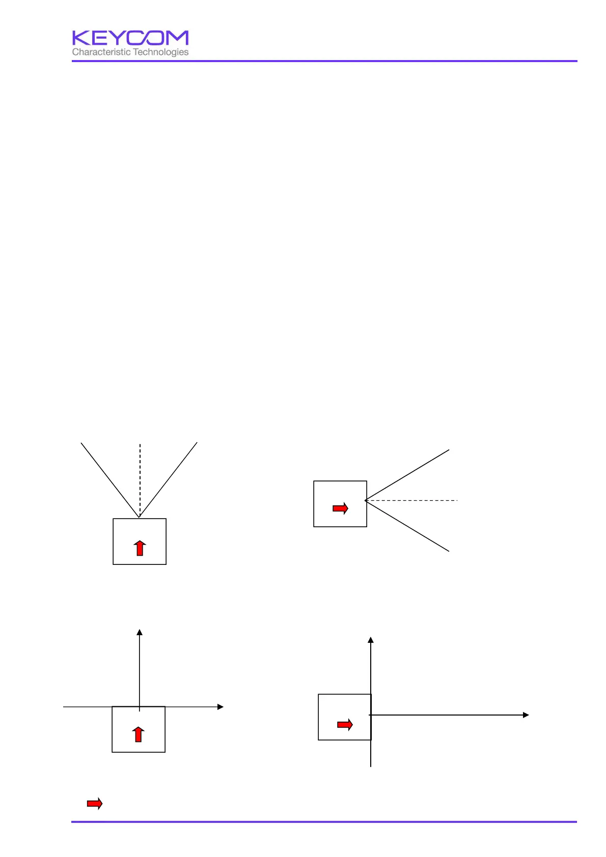
(2) Definition of coordinates
There are three types of coordinate system of the system, polar coordinates, orthogonal coordinates, and cell
coordinates. The definition of each coordinate system is explained below.
Polar coordinate
θ(Theta)、φ(Phi)、d
(d is the distance from the antenna to the target.)
Top view Side view
Cartesian coordinates
x, y, z
Top view Side view
“ “
is the front direction of the radar
RADAR
0°
+θ
-θ
RADAR
0°
-φ
+φ
RADAR
x
z
RADAR
z
y
 Loading...