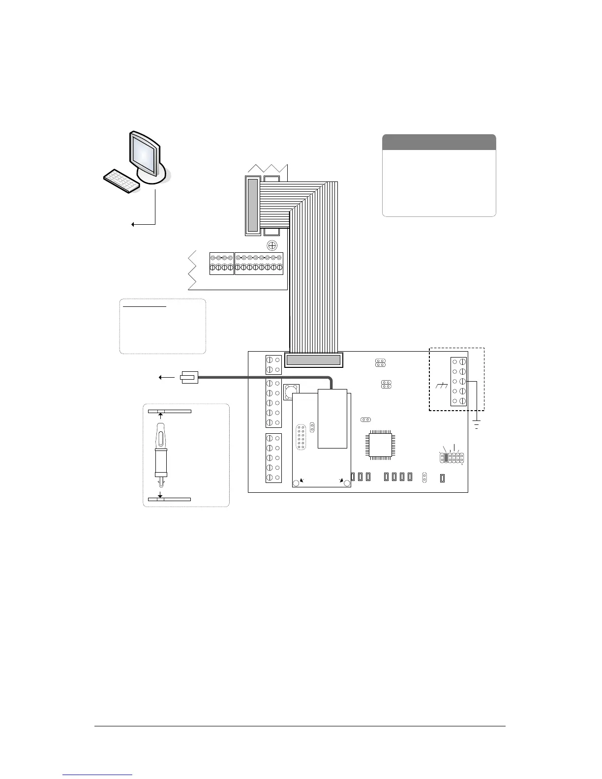
NETCOM6P Operational Connections
Figure 9 and Figure 10 illustrate NETCOM6P operating connections via CIM 0. Refer to the
CIM Guide for complete instructions on setting up and installing CIMs.
Figure 9 – NETCOM6P Mounted on CIM 0
10 or 100 Base T
to
network
or
router
See CIM to CIM
Connections
diagram.
Current Draw - CIM 150 mA + NETCOMP 140 mA = 290mA
KI-00259E-07-12
Connect ribbon cable from
HDR1 on CIM to H2 terminal
on control board.
Jumper ON
J4
TD1
RD1
TD2
RD2
GND
RTS
CTS
GND
RTS
CTS
B3 B2 B1 B0
Diag
J2
RESET
-
CAN2
+
EGND
-
CAN1
+
GND
V +
(+12V)
SCKT1
PC106x
J1
J7
J8
J6
J5
CAN2
CAN1
1 2 1 2 1 2 1 2
Rx-COM
COM
CAN
CAN-Tx
J3
J4
J9
J12
Power
Good
Fault
COM1
COM2
HDR1
J10
J11
Control Board
(PC 109x)
Common AUX Inputs - E
24
2322
2120191817
H1H2
RJ45
Terminal
Jack
J1
U2
NETCOMP
Standoffs
CIM 0
NETCOMP
CIM
Standoff
- correct
mounting
orientation
- RS-232 Data Cable
- Control Board
- PC with network connection
- CIM
- NETCOM2P or NETCOM6P
- 10/100 Base-T Cable
Parts List
to
network
Host PC with
Communication
Manager
Bit Rate / Distance
Bit CAN Bus
9600 3280' (999.7 m)
19200* 3280' (999.7 m)
57600 984' (299.9 m)
115200* 262' (80 m)
* not applicable for reverse
network communication
Note - ensure the NETCOMP version is
a PC1051 or later printed circuit board.
The CIM is not compatible with older
NETCOMP versions.
 Loading...