EasyManua.ls Logo

KHAE GW6 Series - User Manual

KHAE GW6 Series
18 pages
Print Icon
To Next Page IconTo Next Page
Loading...
GW621/GW626/GW631/GW636
Multifunctional pulse meter instruction manual
Pulse counting, rotating pulse measurement and time interval
measurement with high speed plus and minus count
1 Characteristics
18 measuring functions to support all kinds of pulse measurement applications
It can be equipped with voltage-free contacts, photoelectric switches, proximity switches, rotary
encoders and other sensors
High accuracy measurement range 0.0001Hz – 100kHz
Memory function of counting value, maximum value and minimum value, memory/no memory
can be set
Measure value display update cycle, monitor brightness can be set
Two sets of alarm output, alarm type, action error, start delay and close delay can be set
Output function of photoelectric isolation transformer, current output (4-20mA) / voltage output
(0-10VDC)
Photoelectric isolation communication interface RS-485 / RS-232C, with a baud rate range of
2400 ~ 38400bps
2 Model Indication
Dimensions and
Display
Power Sensor Power Alarm Output
1
Alarm Output
2
Relay Output
621
160x80x80mm
4 LED, 20.3mm
1 100 - 240VAC 05 5VDC 0 None 0 None 0 None
631
160x80x80mm
6 LED, 20.3mm
2 24V AC/DC 12 12VDC 1 Relay 1 Relay 1 RS-485
626
96x48x82mm
4 LED, 20.3mm
24 24VDC 2 NPN 2 NPN 2 RS-232C
636
96x48x82mm
6 LED, 14.2mm
3 4-20mA
4 0-10VDC
Question and Answer IconNeed help?

Do you have a question about the KHAE GW6 Series and is the answer not in the manual?

Overview

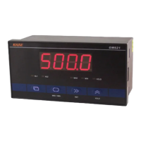
This document describes the GW621/GW626/GW631/GW636 series of multifunctional pulse meters, providing details on their functions, technical specifications, usage, and maintenance.

Function Description:

The GW series pulse meters offer 18 measuring functions (F01 to F18) to support a wide range of pulse measurement applications. These functions are set via the FUNC parameter. The device can be equipped with various sensors such as voltage-free contacts, photoelectric switches, proximity switches, and rotary encoders. It boasts a high accuracy measurement range of 0.0001Hz to 100kHz.

Key functions include:

  • Pulse Counting (F01, F02, F03, F04):

    • F01 - Independent input and subtraction counter: Counts up on the rising edge of IN-1 input and counts down on the rising edge of IN-2 input. If both inputs are connected simultaneously, the count remains unchanged.
    • F02 - Instruction input plus and minus counter: IN-1 input controls the direction (plus/minus), and IN-2 input is counted. When IN-1 is high, counting adds on the rising edge of IN-2. When IN-1 is low, counting subtracts on the rising edge of IN-2.
    • F03 - Phase difference input and addition counter: Counts up on the descending edge of IN-2 if IN-1's pulse phase is ahead of IN-2's. Counts down on the ascending edge of IN-2 if IN-1's pulse phase lags behind IN-2's.
    • F04 - Double input unidirectional counter: Adds count on both IN-1 and the rising edge of IN-2. A negative ratio factor A can be set if the counter needs to subtract.
    • These counting functions use the formula: measurement value = count * A ÷ B + C, where A and B are ratio factors for unit conversion, and C is the initial counter value.
  • Frequency and Speed Measurement (F05, F06, F07, F08):

    • F05 - Tachometer: Measures pulse signals from IN-2 per minute, displaying speed in rpm. Formula: pulse count per minute * A ÷ B.
    • F06 - Frequency table: Measures IN-2 input pulse frequency in Hz. Formula: frequency * A ÷ B.
    • F07 - Cycle: Measures the input pulse period of IN-2. Formula: cycle * A ÷ B (periodic unit: ms).
    • F08 - Duty Cycle: Measures the ratio of IN-2 input pulse width to its period. Formula: duty cycle * A ÷ B (duty cycle:%).
  • Time and Length Measurement (F09, F10, F11, F12, F13, F14):

    • F09 - Through Speed: Multiplies the reciprocal of time t(s) from IN-1 to IN-2 by 60, showing object's passing speed. Formula: 1/t * 60 * A ÷ B.
    • F10 - Transmission Cycle: Displays the time from IN to 2 to the next conduction time t(s). Formula: t * A ÷ B.
    • F11 - Time Difference: Shows the time between IN-1 and IN-2 conduction T(s). Formula: T * A ÷ B.
    • F12 - Time Slot: Displays IN-1 conduction time t(s). Formula: t * A ÷ B.
    • F13 - Measurement Length: Measures length based on pulse inputs.
    • F14 - Time Interval: Measures time intervals.
  • Ratio and Flow Rate Measurement (F15, F16, F17, F18):

    • F15 - Absolute Ratio: Shows the absolute value between frequencies of IN-2 (F2) and IN-1 (F1) in percentage. Formula: (F2 * D ÷ E) / (F1 * A ÷ B) * 100%.
    • F16 - Error Ratio: Shows the error between frequencies of IN-2 (F2) and IN-1 (F1) in percentage. Formula: (F2 * D ÷ E - F1 * A ÷ B) / (F1 * A ÷ B) * 100%.
    • F17 - Rotation Difference: Shows the difference between the speed of IN-2 (N2) and IN-1 (N1). Formula: N2 * D ÷ E - N1 * A ÷ B.
    • F18 - Flow Rate: Shows the flow rate ratio of IN-2 based on the frequencies of IN-2 (F2) and IN-1 (F1). Formula: (F2 * D ÷ E) / (F1 * A ÷ B + F2 * D ÷ E) * 100%.

The device includes memory functions for counting values, maximum values, and minimum values, with configurable memory settings. It allows adjustment of the display update cycle and monitor brightness. Two sets of alarm outputs are available, with configurable alarm type, action error, start delay, and close delay. Output options include photoelectric isolation transformer current output (4-20mA) or voltage output (0-10VDC). Communication is supported via photoelectric isolation interfaces RS-485 or RS-232C, with baud rates ranging from 2400 to 38400bps.

Important Technical Specifications:

  • Models: GW621, GW626, GW631, GW636
  • Panel Size:
    • GW621/GW631: 160 x 80mm
    • GW626/GW636: 96 x 48mm
  • Display:
    • GW621/GW626: 4 bits LED, Red, Height 20.3mm
    • GW631/GW636: 6 bits LED, Red, Height 20.3mm (GW631), 14.2mm (GW636)
  • Display Range:
    • GW621/GW626: -1999 ~ 9999
    • GW631/GW636: -199999 ~ 999999
  • Input: IN-1, IN-2, RST, HOLD. Accepts no voltage contacts, voltage pulses, or collector open circuits. High level input voltage: 4 ~ 30VDC, low level: 0 ~ 1VDC. Minimum width of external reset signal: 20ms.
  • Power Supply (Sensor):
    • 5VDC ±5%, 130mA
    • 12VDC ±5%, 60mA
    • 24VDC ±5%, 30mA
  • Measurement Range:
    • F01/F02/F04: 0-30Hz, 0-3kHz, 0-100kHz
    • F03: 0-30Hz, 0-3kHz, 0-50kHz
    • F05/F06/F07: 0.0001Hz-100kHz
    • F08: 0.0001Hz-50kHz (Square wave)
    • F09/F10/F11/F12: 10ms-9999s
    • F13/F14: 0.01Hz-50kHz
    • F15/F16/F17/F18: 0.01Hz-50kHz
  • Accuracy:
    • F05/F06/F07: ±0.02%rdg ±1digit
    • F08: ±0.05%rdg ±1digit
    • F09/F10/F11/F12: ±0.05%rdg ±1digit
    • F15/F16/F17/F18: ±0.05%rdg ±1digit
  • Data Storage: EEPROM (Nonvolatile memory), rewriting times = 100,000 times.
  • Alarm Output: Relay output: 3A 250VAC / 30VDC (Resistive load), electrical life 1,000,000 times, mechanical life 100,000,000 times. Transistor output: 100mA / 35VDC.
  • Converter Output:
    • Current output: 4-20mADC (0-20mADC, 0-10mADC), Max load resistance 600Ω.
    • Voltage output: 0-10VDC (0-5VDC, 1-5VDC), Min load resistance 2kΩ.
    • Variable output accuracy: ±0.3%FS.
  • Communication:
    • RS-485 (2 lines): Max communication distance 500m, directly connects to 63 meters at most.
    • RS-232C (3 lines): Max communication distance 15m.
    • Baud rate: 2400, 4800, 9600, 19200, 38400bps.
  • Power Supply (Main):
    • 100-240VAC, allowed band 85-264VAC 50/60Hz
    • 24V AC/DC, allowed band 20-55VAC 50/60Hz
    • 20-75VDC
  • Consumption: <5W
  • Temperature: Working: 0-50°C, Storage: -20-70°C
  • Humidity: ≤85%
  • Environment: Indoor, no dust, no water drops, no oil mist, no corrosion, no serious vibration and impact.

Usage Features:

  • Panel Operation: The front panel features a display window and buttons for setting parameters.
    • Display: In normal mode, it shows measured values (current, maximum, minimum). "HHHH" or "LLLL" indicates exceeding the display range. In setup mode, it displays parameter symbols and values.
    • Buttons:
      • MAX/MIN (key 8): Switches between current, maximum, and minimum values. Pressing for >3 seconds resets max/min values to the current value.
      • RST (key 9): Resets the measured value and instrument output, stopping measurement.
      • HOLD (key 10): Prohibits IN-1 and IN-2 inputs, holding the current measurement value and output. The HOLD indicator light illuminates. Pressing again exits the hold state.
      • Menu (key 7): Enters the menu system.
      • Increase Key / HOLD (key 10): Used to increase values in setup mode.
      • Shift Key / RST (key 9): Used to shift digits or reset in setup mode.
    • Menu Structure: Parameters are organized into Operation Menu, Engineer Menu, and Configuration Menu.
      • Operation Menu: For frequently changed parameters (0-8 user-selected).
      • Engineer Menu: For measurement, control, and display parameters.
      • Configuration Menu: For instrument function and input signal range, typically not modified after installation.
    • Parameter Setting: Enter a menu, select a parameter, display its code value (flashing if editable), use and to adjust, then SET to save. The meter returns to normal mode if no button is pressed for 1 minute during setting. Unsaved changes are lost.
    • Passwords: PAS1, PAS2, PAS3 parameters can be set to require a password before entering corresponding menus.
  • Input Signal Logic Reversal (IN-N, RH-N): Allows inversion of input signal logic for IN-1, IN-2, RST, and HOLD inputs.
  • Digital Filter (FILT): Adjustable coefficient (0-9). A larger value provides more stable readings but slower response, useful for noisy signals.
  • Automatic Reset Time (ATZ1, ATZ2): If no pulse input occurs within this time, the value is forced to 0.
  • Measure Delay Time with Power On (MDLY): Sets a delay for the instrument to wait for a stable input signal after power-up.
  • Power Out Storage (MEMO): When ON, the instrument remembers measurements before power loss and resumes counting from that value. When OFF, no memory is retained.
  • Output Test (TEST): Allows simulation of measurement values via key operation to check output actions without actual input signals.
  • Display Update Cycle (DREF): Adjustable (50ms to 4s). Increasing the cycle can improve readability for rapidly changing values.
  • Alarm Action Error (ALY1, ALY2): Prevents repeated alarm actions due to input fluctuations when the measured value is near the alarm threshold.
  • Alarm Delay Times (ALN1, ALN2, ALF1, ALF2): Start delay (ALN) and close delay (ALF) for alarms. The alarm action occurs after the delay time. If the condition is no longer met during the delay, no alarm action occurs.
  • Ratio Factor (A, B, D, E): Used to convert count values into desired units for display.
  • Decimal Point Position (DP): Configurable to adjust the decimal point in the displayed value.
  • Sensor Type: The instrument is equipped with an NPN type sensor. For PNP sensors, customization is required.

Maintenance Features:

  • General Precautions:
    • Read instructions carefully before use.
    • Use in a standard environment (temperature, humidity, etc.).
    • Do not close the meter; ensure adequate space for heat dissipation.
    • Do not disassemble the meter to avoid electric shock or malfunction.
    • Disconnect power before wiring, installing, or disassembling.
    • Avoid touching live parts or power terminals.
  • Interference Mitigation:
    • Install a power filter close to the instrument.
    • Connect a capacitor (100pF to 1F) to the signal input terminal to filter high-frequency interference. The capacitance affects the maximum measurement frequency.
    • Avoid installing near high-frequency generators (converters, motors, welding machines, transformers).
    • Route signal lines separately from high-voltage/current power lines, keeping them short and using shielded cables for extensions.
  • Password Reset: If menu passwords are forgotten, contact the manufacturer or distributor to restore factory values.
  • EEPROM Lifespan: EEPROM has a limited number of write cycles (approx. 100,000). For parameters with frequent changes, it's recommended to write to RAM without write limits. However, on power-up, the instrument uses data from EEPROM.
  • Communication Modes (COMM):
    • OFF: Communication function is closed.
    • RO (Read Only): Parameters and working status can be read but not modified.
    • R-W (Read/Write): Parameters and working status can be read and modified.
  • Warranty: 18 months from the date of sale, with lifelong maintenance. Covers breakdowns/damage under normal use. Excludes damage from improper custody, use, accidents, or transportation/on-site service costs. Maintenance services for excluded damages are available for a reasonable charge.

KHAE GW6 Series Specifications

General IconGeneral
BrandKHAE
ModelGW6 Series
CategoryMeasuring Instruments
LanguageEnglish