Do you have a question about the Kidco Safeway G2000 and is the answer not in the manual?
Gate must be installed in a structurally sound opening on a rigid surface.
Gate placement on stairs: top stair or bottom stair.
Mount hinge side template (A) vertically on rigid surface.
Mount locking side template (B) vertically on rigid surface.
Open gate by pressing latch and lifting; ensure it's locked when not in use.
Follow instructions, check stability, prevent injury, never leave child unattended.
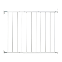
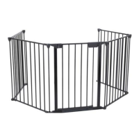
This document describes the KidCo Safeway Hardware Mount Installation gate, models G2000 and G2001, designed for openings between 24.75" and 43.5". This gate is JPMA certified and conforms to ASTM F1004 Safety Standards.
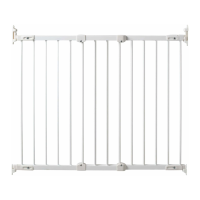
The gate's primary function is to provide a safety barrier for children aged 6 to 24 months. It is a hardware-mounted gate, meaning it is permanently affixed to a structurally sound opening, such as a wall, door frame, or stairposts. This type of installation ensures a rigid and secure barrier, crucial for preventing serious injury or death. The gate is designed to be installed in a structurally sound opening, with the hinge side mounted to a rigid surface. It is important to ensure that the mounting surface is strong, rigid, and has an even surface to guarantee proper installation and stability.
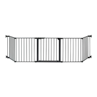
When installing the gate on a stairway, it must be placed either on the top stair or on the lowest stair at the bottom. This specific placement is critical for safety, especially at the top of stairways, where the gate should never open out over the stairs. The gate's design allows for adjustment to achieve the correct width for various openings. This is accomplished by adjusting the gate sections and all four corner spindles. Each spindle can be individually extended to accommodate molding, uneven walls, or other irregularities in the opening. The hinge side spindles can be extended a minimum of 1 1/4" and a maximum of 3", while the locking side spindles can be extended a minimum of 1" and a maximum of 3".
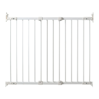
The installation process involves several steps to ensure proper fit and security. First, the gate sections are adjusted until the gate is approximately the correct width, and the adjustment holes are aligned and overlap in two places on both the top and bottom rails. The maximum overlap allowed is 5 bars, and sections should fit without any distance between rails or bars. Screws and screw sockets are then placed in the top and bottom sets of overlapping adjustment holes nearest the hinge and locking sides of the gate, though they are not fully tightened at this stage.
Next, the upper hinge spindle (H) is screwed into the top rail of one gate section, and the lower hinge spindle (D) is screwed into the bottom rail of the same side. Both spindles should be extended equally. For the locking latch spindles (N), they are screwed into the top and bottom rails of the second gate section and extended equally. Final spindle adjustments will be made later in the installation process.
Mounting the hinge side involves using templates (A) to mark screw hole positions. The template (A) is held vertically and completely outstretched against the mounting surface, with the end marked "I" even with the floor. For mounting into wood, the provided screws are used. If mounting into brick, drywall, or other surfaces, appropriate hardware must be used. If installing into hardwood (e.g., oak), drilling a pilot hole may be necessary. The upper hinge (G) is mounted with two wood screws (K) in the top two screw hole positions, with the hole pointing up. Similarly, the lower hinge bottom (C) is mounted with two wood screws (K) in the bottom two screw hole positions, with the post pointing up. Longer screws may be required if mounting into studs behind drywall.
For the locking side mounting, template (B) is used to mark four screw hole positions. Template (B) is held vertically and completely outstretched against the mounting surface, with the end marked "I" even with the floor. Similar to the hinge side, appropriate hardware is used based on the mounting surface. Before mounting the latch brackets, the desired opening direction of the gate must be determined. For the top of stairways, the gate should never open out over the stairs. Stop pins (O) are inserted from behind into the holes of the locking latch bracket (L) and lower latch bracket (M) opposite the desired opening direction. It is important to note that the gate cannot open to the stop pin side. The locking latch bracket (L) is mounted with two wood screws (K) in the top two screw hole positions, and the lower latch bracket (M) is mounted with two wood screws (K) in the bottom two screw hole positions.
Once the brackets are mounted, the gate is centered in the opening. The upper hinge spindle (H) is adjusted so that its post fits into the upper hinge hole (G). The lower hinge spindle (D) is adjusted so that its end fits over the lower hinge post (C). The space between the end of the gate and the mounting surface on the hinge side should be no less than 1 1/4" and no more than 2 1/2". The locking latch spindles (N) are then adjusted until they fit securely into both latch brackets. The top spindle must click under the locking latch when the gate is in the closed position. The space between the end of the gate and the mounting surface on the locking side should be no less than 1" and no more than 2 3/4". If adjusting the spindles does not achieve the correct length, it may be necessary to lift the gate off its hinges and readjust the sections as described in step 3. After these adjustments, the gate should be checked to ensure it can be smoothly opened and closed.
A spring (E) is placed on the lower hinge post, followed by the lower hinge cap (F), which is pushed down until it clicks into a locked position. It is crucial to ensure that the hinge cap cannot be pushed up and is securely locked in place. Finally, all screws and screw sockets are tightened using a Phillips head screwdriver, and all four lock nuts are securely tightened toward the gate using a wrench (P).
To operate the gate, press down on the locking latch with your thumb and lift the gate out of the upper and lower brackets. To lock the gate, the top locking latch spindle must click under the locking latch, and the bottom latch spindle must rest in the bottom bracket, as shown in figure 17 in the manual. The gate should always be in the locked position. Excessive pressure, such as standing or swinging on the gate when it is open, can cause structural damage.
For temporary removal, the gate can be disengaged by pressing back on the locking tab on top of the lower hinge bottom while sliding the hinge cap up. The spring is then removed, and the gate is lifted off the top and bottom hinges. For safety reasons, the spring and hinge cap must be returned onto the hinge post, and the cap must be locked in place.
Maintenance of the gate is straightforward. No part of the gate requires lubrication. It should be cleaned using warm, soapy water or a damp cloth. Abrasive cleaners or bleach should not be used. After installation, the gate should be checked periodically to ensure a safe and secure fit and to maintain proper working order.
Important safety warnings accompany the gate. It is intended for use with children from 6 months through 24 months. Users must regularly check the stability of the gate and tighten all hardware and mountings. To prevent serious injury or death, the gate or enclosure must be securely installed and used according to the manufacturer's instructions. The gate should never be used with a child able to climb over or dislodge/open it. It should not be used if the gate is less than 3/4 of the child's height or if any part of the gate is broken or missing. This product does not necessarily prevent all accidents, and a child should never be left unattended. Only spare parts available from KidCo® should be used. Children should never be allowed to climb or swing on the gate. The gate should only be used with the locking/latching mechanism securely engaged. Discontinue use if any part of the gate is damaged. Children should never climb over the gate, and toys or other items should never be hung or tied to any part of the gate.
| Product Type | Safety Gate |
|---|---|
| Material | Metal |
| Height | 30.5 inches |
| Installation Type | Hardware Mounted |
| Color | White |
| Mounting | Wall |