4-13
September 2004 90-FM200M-000
FM-200
®
ECS Series Engineered Fire Suppression Systems
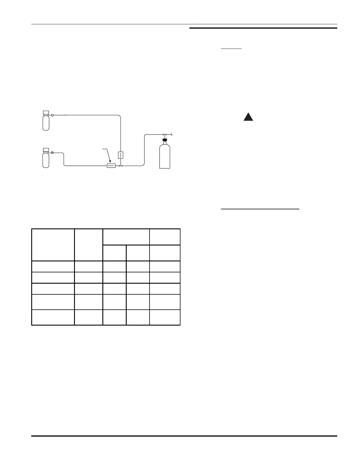
4-2.5.5 USING MULTIPLE NITROGEN CYLINDERS
Two or more remotely located pilot nitrogen cylinders can
be used to actuate the FM-200 systems described in Para-
graphs 4-2.5.3 and 4-2.5.4, provided that:
1/4" check valves (P/N 264985) shall be installed
at the intersection of each pilot line to the main ac-
tuator line (see Figure 4-9).
The total length of actuator line, from each nitro-
gen pilot cylinder to the FM-200 cylinders shall not
exceed the limitation established.
N PILOT
CYLINDER
2
N PILOT
CYLINDER
2
¼” CHECK VALVE
P/N WI-264985-000
FM-200
CYLINDER
Figure 4-9. Multiple Pilot Nitrogen Actuation Cylinders
4-2.5.6 CORNER PULLEY AND
CABLE LIMITATIONS
Table 4-7 lists corner pulley and cable length limitations.
Table 4-7. Corner Pulley and Cable Limitations
Control Head
Type
Part
Number
Pulley
Max. Cable
Length
P/N
803808
P/N
844648
ft.
Cable Operated 979469 15 30 100
Electric/Cable 895630 6 30 100
Electric/Cable 895627 6 30 100
Electric/Cable,
Explosion-Proof
897494 6 30 100
Electric/Cable,
Explosion-Proof
897560 6 30 100
4-2.5.7 PRESSURE TRIP LIMITATIONS
The maximum load to be attached to pressure trip
(P/N 874290) is 100 lb. (45.3 kg, based on a minimum pres-
sure of 75 PSIG [5.17 bar gauge] at the pressure trip).
4-3 EQUIPMENT INSTALLATION
4-3.1 General
All Kidde FM-200 equipment must be installed to facili-
tate proper inspection, testing, manual operation, re-
charging and any other required maintenance as may
be necessary. Equipment must not be subject to severe
weather conditions or mechanical, chemical or other
damage that could render the equipment inoperative.
Equipment must be installed in accordance with
NFPA Standard 2001, current edition.
WARNING
!
The FM-200 cylinder/valve assemblies must be
handled, installed and serviced in accordance
with the instructions contained in this
paragraph and Compressed Gas Association
(CGA) pamphlets C-1, C-6 and P-1. CGA
pamphlets may be obtained from: Compressed
Gas Association, 1235 Jefferson Davis
Highway, Arlington, VA 22202. Failure to follow
these instructions can cause FM-200 cylinders
to violently discharge, resulting in severe injury,
death and/or property destruction.
4-3.2 Distribution Piping and Fittings
4-3.2.1 THREADS
Threads on all pipe and fittings must be tapered threads
conforming to ANSI Specification 8-20.1. Joint compound,
tape or thread lubricant must be applied only to the male
threads of the joint.
4-3.2.2 PIPE
Piping must be of noncombustible material having physical
and chemical characteristics, such that its integrity under
stress can be predicted with reliability. The computer flow
program has only been verified for the specific types and
schedule of pipe and fittings covered in this manual. There
is a risk that the system may not supply the required quan-
tity of agent in unbalanced systems when other pipe types
and fittings are used.
 Loading...