2 / 6 P/N 3101069-EN • REV 005 • ISS 19OCT20
Selecting an appropriate sampling tube:
• Select a sampling tube that extends at least two-thirds across
the width of the duct. Refer to Table 3 below.
• For duct widths greater than 36 inches, use a sampling tube that
is longer than the width of the duct.
• Sampling tubes are available in the following lengths:
Table 3: Sampling tubes
-T8 8 SD-T42 42
-T18 18 SD-T60 60
-T24 24 SD-T78 78
-T36 36 SD-T120 120
To assemble the detector:
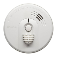
1. Assemble the duct smoke detector as shown in Figure 1.
2. Rotate the air sampling tube so the inlet holes face the direction
of airflow.
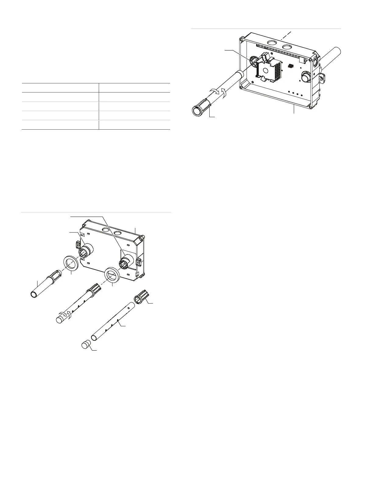
3. The sampling tube is normally installed from the rear, but it can
also be installed from the front of the detector as shown in
Figure 2. This method requires that you remove the detector
cover.
Figure 1: Duct detector assembly
(1) Exhaust tube socket
(2)
Sampling tube socket
Detector
Coupling
Thick gasket
Thin gasket
Exhaust tube
Figure 2: Sampling tube installation
(1) Sampling tube socket
(2)
Detector
(3) Sampling tube (fully assembled)
To install the detector:
1. Attach the drill template to the HVAC duct at the desired
mounting location.
2. Drill (or punch) the mounting holes where indicated.
3. Remove any rough edges from the holes.
4. When using an air sampling tube that is longer than the width of
the duct:
• Drill a 3/4 in. hole on the opposite side of the duct for the
tube to pass through.
• Cut the tube so that approximately one inch of the tube
extends through the duct. Seal the opening around the
tube with an approved duct sealant as shown in Figure 3.
Note: Support sampling tubes longer than 36 inches at both
ends of the duct. See Figure 3.
5. Mount the duct smoke detector on the HVAC duct and secure it
using the two sheet metal screws provided. See Figure 4.
7. Verify that all field wiring is free of opens, shorts, and ground
faults.
8. Make all wiring connections as shown in Figure 6.
9. Set the module address as follows:
• Use a screwdriver to adjust the two rotary switches on the
front of the module. See Figure 5.
• Set the TENS rotary switch (0 through 12) for the 10s and
100s digit.
• Set the ONES rotary switch for the 0 through 9 digit.
For example: for device address 21, set the TENS rotary switch
to 2, and then set the ONES rotary switch to 1.
For a list of detector addresses, see Table 4 on page 3.
10. Set jumper JP3 to the appropriate position. See Table 1 and
Figure 6.
11. Verify that the air pressure differential value falls within the
specified operating range of the detector in accordance with
procedures specified in “Verifying the air pressure differential”
on page 4.
12. After completing the installation of the duct smoke detector, test
the detector in accordance with procedures specified in “Testing
the duct smoke detector” on page 5 to ensure it is operating
correctly.
(1)
(2)
(3)
(4)
(5)
(6)
(7)
(8)
(9)