Do you have a question about the Kieback & Peter RPW301-FTL and is the answer not in the manual?
| Supply voltage | 24 V AC/DC |
|---|---|
| Housing Material | Plastic |
| Control Algorithm | PID |
| Display | LCD |
| Storage Temperature | -20…70 °C |
| Relative Humidity | <95 % r.H., non-condensing |
Explains graphical symbols and signal words used for safety information.
Provides essential safety guidelines to prevent personal injury and device damage.
Defines the intended purpose and limitations for the en:key room set devices.
Discusses high-frequency emissions from wireless technology and health considerations.
Outlines how user data is handled and protected according to regulations.
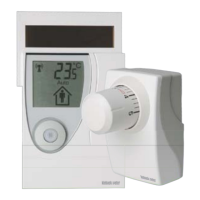
Details the operating and functional components of the valve controller unit.
Details the operating and functional components of the room sensor unit.
Indicates wireless connection status and potential malfunctions.
Shows the status of the energy storage unit for the room sensor.
Signals a rapid temperature drop detected by the sensor.
Displays various status messages and error codes.
Indicates that valve controllers can be registered or are being registered.
Shows room temperature, time, or operational messages.
Indicates the heating time profile is active, either default or learned.
Shows the solar cell is active or the system is in summer mode.
Signals occupancy detection, presence/absence, or vacation mode status.
Displays the current time in HH:MM format.
Indicates the room temperature is displayed in degrees Celsius.
Ensures the occupancy sensor functions correctly by testing the installation location.
Procedure for pairing one or more valve controllers with the room sensor.
Instructions for securely attaching the room sensor to the wall.
Details on attaching the valve controller to the radiator valve.
Guides on adjusting the desired comfort temperature using the rotary knob.
Explains how to switch between comfort and economy modes manually.
Instructions for managing vacation mode, including setting duration.
Details the process for updating the time and date settings on the device.
Describes switching the display between room temperature and time.
Procedure for resetting the room sensor to its original factory settings.
Explains how to switch off both the room sensor and the valve controller.
Guides on activating the service level for advanced functions.
Procedure for removing paired valve controllers from the room sensor.
Shows the last 4 digits of the radio ID and the number of the valve controller.
Displays the software version for processor 1 and processor 2 of the room sensor.
Provides information on various system states, including connection and sensor status.
Details detected malfunctions like transmission errors and system time issues.
Provides guidance on cleaning, proper disposal, and maintenance of the devices.
Presents detailed technical specifications and dimensions for the devices.
