10 11
KWT-555-IML23 Kielder WT Ltd Kielder WT Ltd KWT-555-IML23
(A)
(C)
(D)
(E)
(F)
USAGE
Installing Grease Cartridge
Removing Grease Cartridge
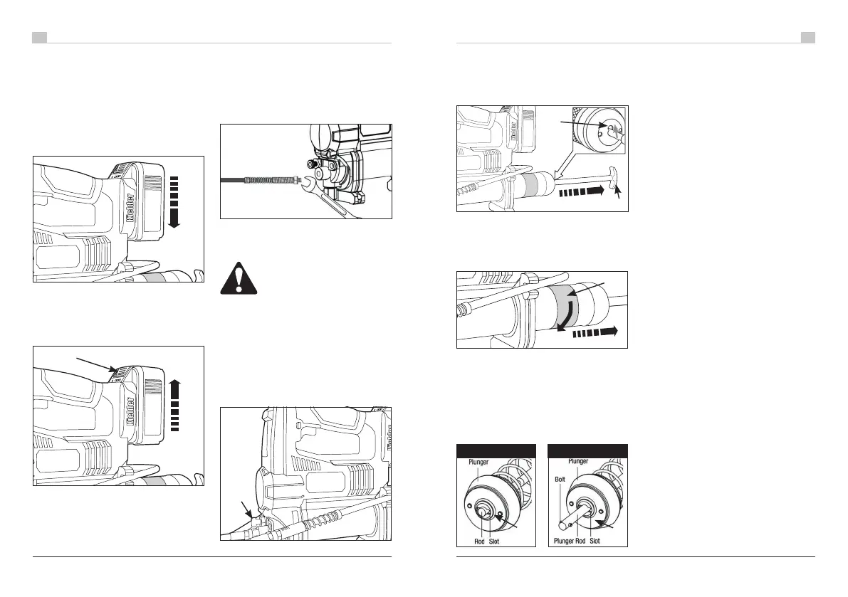
Attaching or Removing the
Battery Pack
Connect The Battery Pack:
Line up the alignment channels and slide
on the battery pack.
Slide the battery pack until it locks into
position with an audible “CLICK”.
Attaching the Flexible Hose
Using a 14mm wrench / spanner, attach the
hose to the front of the machine as shown
below. Nip the fastening to fully seal the
copper washer agains the casting, taking
care not to overtighten and strip the threads.
Remove The Battery Pack:
Depress the button (A) at the front of the
battery indication panel and slide the
battery pack out.
• Remove battery pack and engage the trigger
lock (B).
• Unscrew the brass air bleed valve (C)
around 3 full turns, do not remove.
• Remove battery pack and lock the trigger (B)
• Unscrew the air bleed valve (C) around 3
full turns, do not remove.
• Pull the handle as far as out it will go (D)
and secure the rod by angling the rod into
the keyway on the rear of the barrel cap (E)
• Grip the knurled / textured section of the
barrel (F) and fully unscrew by turning
anti-clockwise. Withdraw the barrel fully
away from the main body, taking care not to
dislodge the rod from the keyway (E).
• Release the rod from the keyway by pulling
and moving back into the centre of the
barrel, allow the rod and plunger to slide
through the barrel; ejecting the empty
cartridge.
• Pull the handle as far as out it will go (D)
and secure the rod by angling the rod into
the keyway on the rear of the barrel cap
(E) This secures the mechanism, ready for
dettaching the barrel from the main body.
• Grip the knurled / textured section of the
barrel (F) and fully unscrew by turning anti-
clockwise. Withdraw the barrel fully away
from the main body, taking care not to
dislodge the rod from the keyway (E).
• Remove the plastic cap from the grease
cartridge and insert (this end rst) into the
barrel.
• Once the cartridge is fully inserted into
the barrel, remove the seal piece from the
cartridge, usually a ring pull or similiar.
• Ret the barrel into the main machine body
and tighten (clockwise) into place.
• Release the rod from the keyway by pulling
and moving back into the centre of the
barrel, this will then part pressurise the
system.
• Complete the process by pushing the
handle rmly and moving the rod into the
barrel, the plunger will then pressurise
the system further, continue pushing until
grease starts to emit from the bleeder valve.
• Now tighten the bleeder valve and the unit
is ready to be primed (see section prime the
the grease gun).
• Once the gun is pressurised and operating
properly, the handle can be rotated to
engage the slide setting (H) this allows
the rod to slide into the barrel, rather than
protruding into the work area.
Whenever the barrel is removed check the rod
and plunger are in the ‘Pressure’ position (G)
where the bolt on the plunger rod is turned
90 degrees inside the plunger, and cannot
move through the slot. If the plunger rod is in
the ‘Slide’ setting (H) then the grease will not
pressurise properly and fail to pump.
CAUTION!
DO NOT USE ANY OTHER
SUBSTANCE OTHER THAN
GREASE. Installing Sealants or Adhesive
type products will cause the unit to fail.
IMPORTANT
This grease gun is compatible with standard
sized 400ml grease cartridges.
IMPORTANT
PRESSURE POSITION SLIDE SETTING
(G)
(H)
14mm
 Loading...