© 2021 Carrier. All rights reserved. 1 / 4 P/N 20-8030-501-1000-09 • ISS 03NOV21
D1115-5
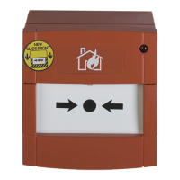
KAL455 Manual Call Point Installation Sheet
EN FR
EN: Installation Sheet
Description
This document includes installation information for KAL455
manual call points. These manual call points are designed for
use in Kilsen addressable fire alarm systems and include
models for indoor and outdoor use.
Installation
Caution: This product must be installed by qualified personnel
adhering to the CEN/TS 54-14 standard and any other
applicable local authority laws.
Electrical connections
Connect to the KAL455 connection block (Figure
2) as follows:
1. Line in (positive)
2. Line out (positive)
3. Line in (negative)
4. Line out (negative)
Addressing
Use the DIP switch (Figure 1) to allocate a device address
from 128 to 252 (see page 4).
Maintenance
Basic maintenance consists of a yearly inspection. Do not
modify internal wiring or circuitry.
Caution: When changing the resettable element from glass to
flexi, press the element after installation to confirm the
operation.
Specifications
22 to 35 VDC
Standby
Alarm
max. 250 ųA
max. 2.5 mA
Minimum
Maximum
0.8 mm
2
2.5 mm
2
KAL455
KAL455E
IP24D
IP67
KAL455
KAL455E
−10°C to +55°C
−25°C to +70°C
KAL455
KAL455E
−10°C to +70°C
−25°C to +70°C
10% to 95% noncondensing
x H x D)
KAL455
KAL455E
89 x 93 x 27.5 mm [1]
97.5 x 93 x 27.5 mm [1]
KAL455
KAL455E
180 g
350 g
[1] Excluding surface mount.