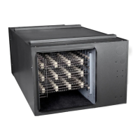
MAU Installation Manual
Page
18
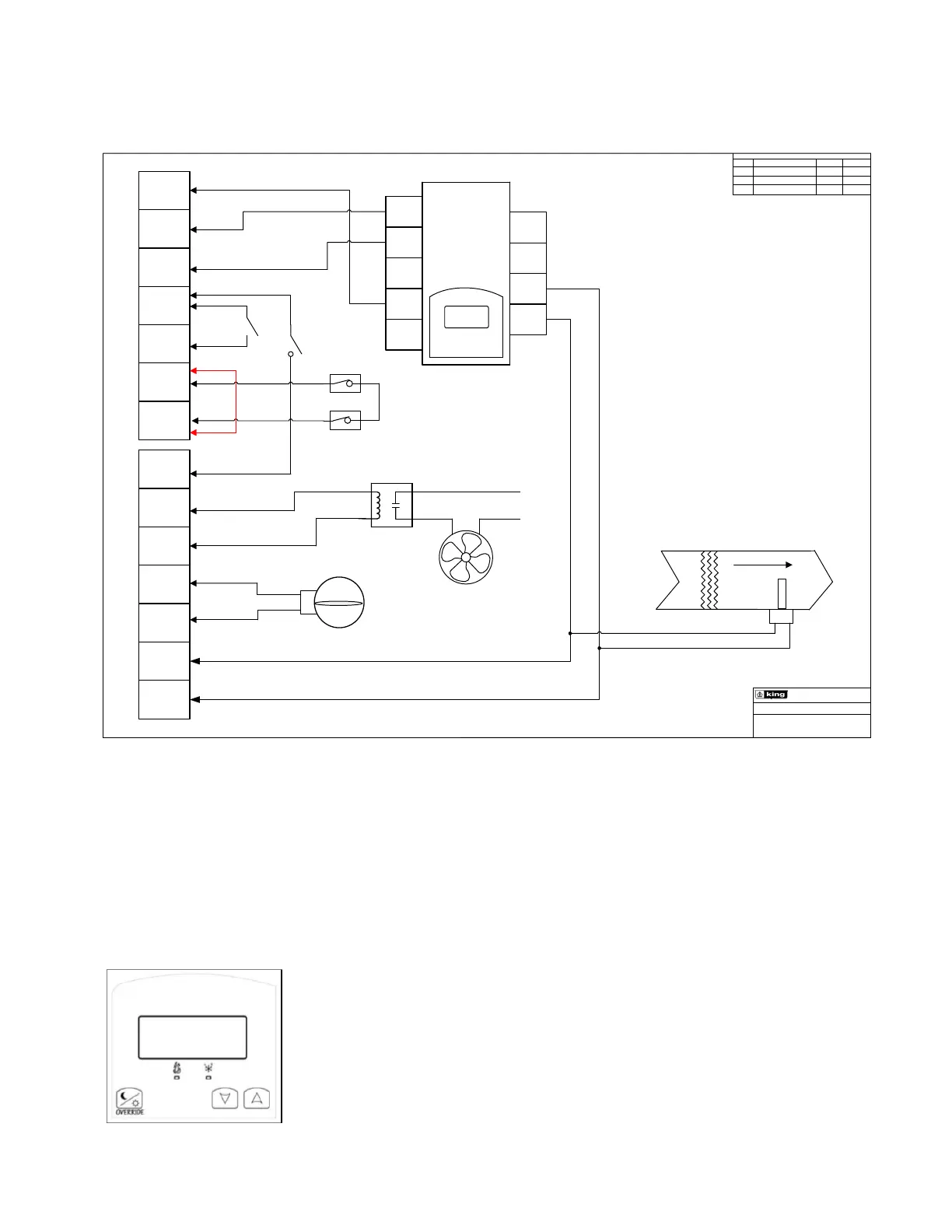
LOW VOLTAGE CONTROL SCHEMATIC
REV
DESCRIPTION
DATE
BY:
1
INITIAL RELEASE
04-22-20 DW
FILE: MAU EXT. CONTROL DIAGRAM
ELECTRICAL MFG
A0
24V
HOT
24V
COM
R1
R2
L
L
G
EF
24V
EF
COM
D
24V
D
COM
JUMPER
MAKE UP AIR UNIT, EXTERNAL LOW
VOLTAGE CONTR OL DIAGRAM
AO 1
AO 2
AUX
24V
COM
24V
HOT
UI 3
S
COM
RS
BI 1
VICONICS
VT7225
DUCT SENSOR
FAN RELAY
24VAC
L1
L2
EXHUAST
FAN
0 to 10 VDC SIGNAL
FAN ONLY
ON /OFF
OUTDOOR THERMOSTAT &
HUMIDISTAT
MOTORIZED
DAMPER 24VAC
Notes:
1. AO2 is the default setting when using a duct
sensor.
2. Mount Duct Sensor a minimum of 3 feet from
the MAU supply side.
3. ON/OFF control by closing R1
-R2
4. Remove the RED jumper wire between L-L
to enable the lock out circuit, heater will not turn
on unless L
-L is closed.
5. 24VAC power is provided to EF
-EF when
R1-R2 (Heat) or R1-G (Fan only) are closed.
Typically used to turn on an exhaust fan by
applying power to a relay coil.
6. 24VAC power is provided to D-D when R1-
R2 (Heat) or R1
-G (Fan only) are closed.
Used to open a 24VAC motorized Damper with
spring return.
DS
DS
Mount the Duct Sensor a minimum
of 3 ft from the MAU supply side.
MODULATING THERMOSTAT CONTROL
The VT7225 series controllers are microcomputer-based, proportional and integral (PI) devices with
one analog 0 to 10 Vdc output, one 8 Vdc and one 24 Vac proportioning pulsed output.
The King MAU uses the analog 0 to 10 Vdc modulating output to control the room or supply air
temperature by modulating directly a 0 to 10 Vdc SCR power controller.
Adjust the temperature set point by pushing the up and down arrows.
An Override can be made during an unoccupied period. If the Override
option is enabled in the lockout configuration pressing the override key
will resume occupied setpoints for a time specified by parameter
ToccTime. Refer to the Viconics VT7225 Series User Guide for
additional information.
 Loading...