KINROAD 150 SERVICE MANUAL VERSION 1, DEC., 2005
43
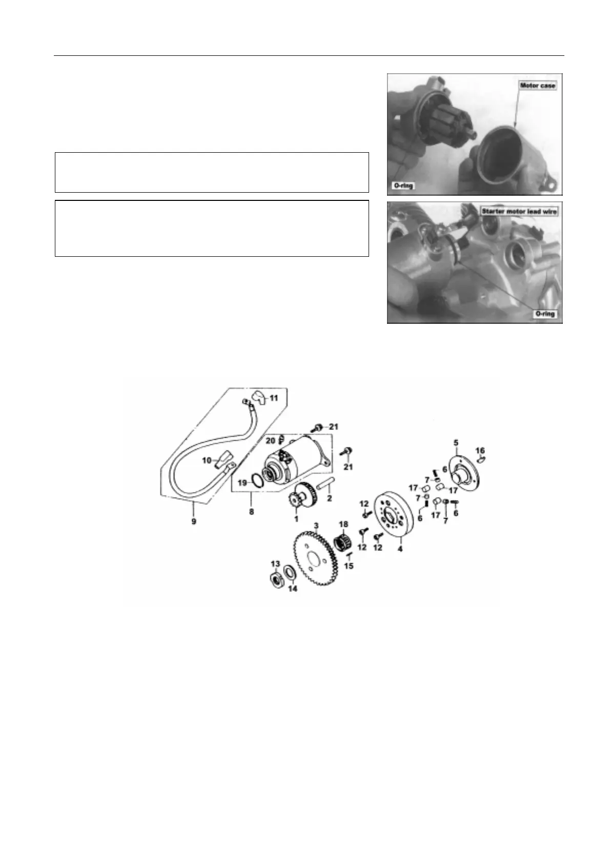
Assemble the new O-ring on the carbon brush base.
Install armature into starter motor case, making sure not to damage
the carbon brushes.
Tighten motor case bolts.
Apply oil on the O-ring, and install the starter motor. Tighten holding
bolts.
REDUCTION MECHANISM
The picture shows the structure of the reduction mechanism.
1. Starter reduction gear 11. Clamp
2. Starter reduction gear shaft 12. Bolt
3. Starting clutch gear comp. 13. Nut
4. Starting clutch outer comp. 14. Washer
5. Flange starting clutch 15. Dowel pin
6. Starting clutch roller spring 16. Key woodruff
7. Spring holder 17. Roller
8. Starter motor 18. Needle bearing
z Make sure the starter motor case is free of metal particles,
because it is magnetic.
z Before installing the starter motor on the vehicle after
assembling it, first connect the lead wires and inspect if
the motor runs normally.
 Loading...