KINROAD 150 SERVICE MANUAL VERSION 1, DEC., 2005
74
5. CHASSIS
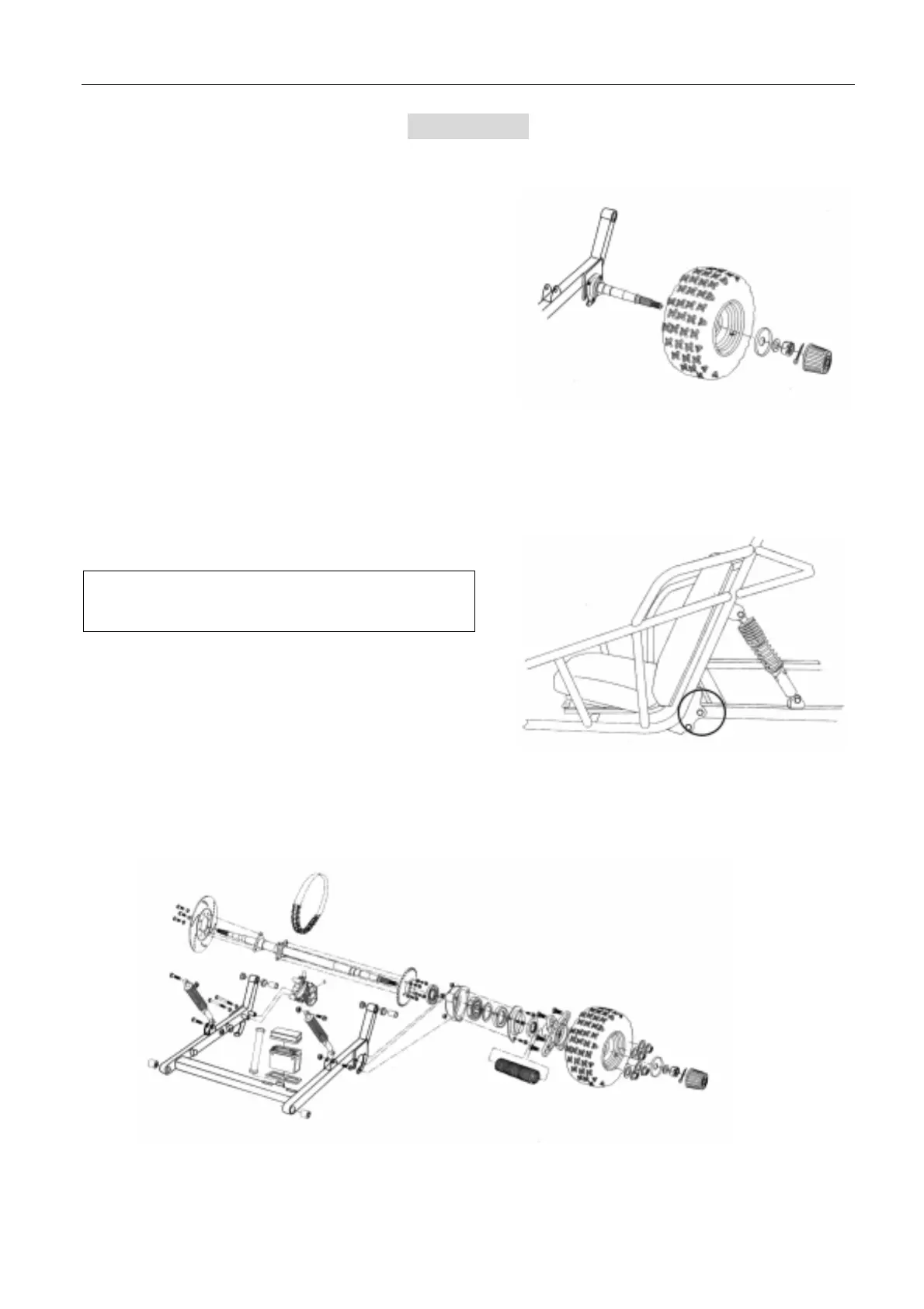
REAR AXLE REMOVAL
z Disassemble RR. Wheel
z Remove the Cotter Pins on Axle Nut, RR Wheel
z Remove the Axle Nut, RR. Wheel.
z Block up rear end of the machine.
z Remove rear wheel and hub assembly by sliding off
splines of axle.
z Remove the chain.
z Loosen nuts on bearing carrier and remove bolts.
z Remove axle and bearing carriers as a unit.
REAR. SWING ARM
z Remove Rear. Shock.
z Remove rear brake caliper and set aside.
Do not remove brake hose!
z Unplug brake light wiring from the electrical box.
z Remove throttle cable.
z Remove bolts from swing arm pivot
z Check Buffer Rubber Bushing for wear. If wear is present on bushing, it should be replaced.
Note: Swing arm, axle and motor can be removed
as a unit if needed.
 Loading...