ALWAYS fasten the slotted nut firmly, then insert and bend the split pin completely.
(6) Mounting trolley to traversing rail
Remark : For larger Capacity hoists (7.5t and larger), refer to the ERML-9806-MC manual.
(a) Mounting to traversing rail .
1) Slide the trolley with an electric chain hoist connected onto the traversing rail from the rail end. This is
the most convenient and recommended way.
2) When the connected unit can not be mounted onto the rail sliding from the rail end, follow the next
steps referring to Fig.5-9.
a) Remove the stopper pin from hole A and insert it into hole B of the suspension shaft. Reinsert and
bend it fully.
b) With the side plates S and G spread outward, lift the trolley until the track wheels are on the same
level of the rail surface (tread), and place the track wheels of side plate G on the rail tread.
c) Holding the side plate G securely so that it does not come off the rail, push the side plate S to put its
wheels onto the rail tread.
d) Remove the stopper pin from hole B and insert it into hole A, and bend the split pin securely.
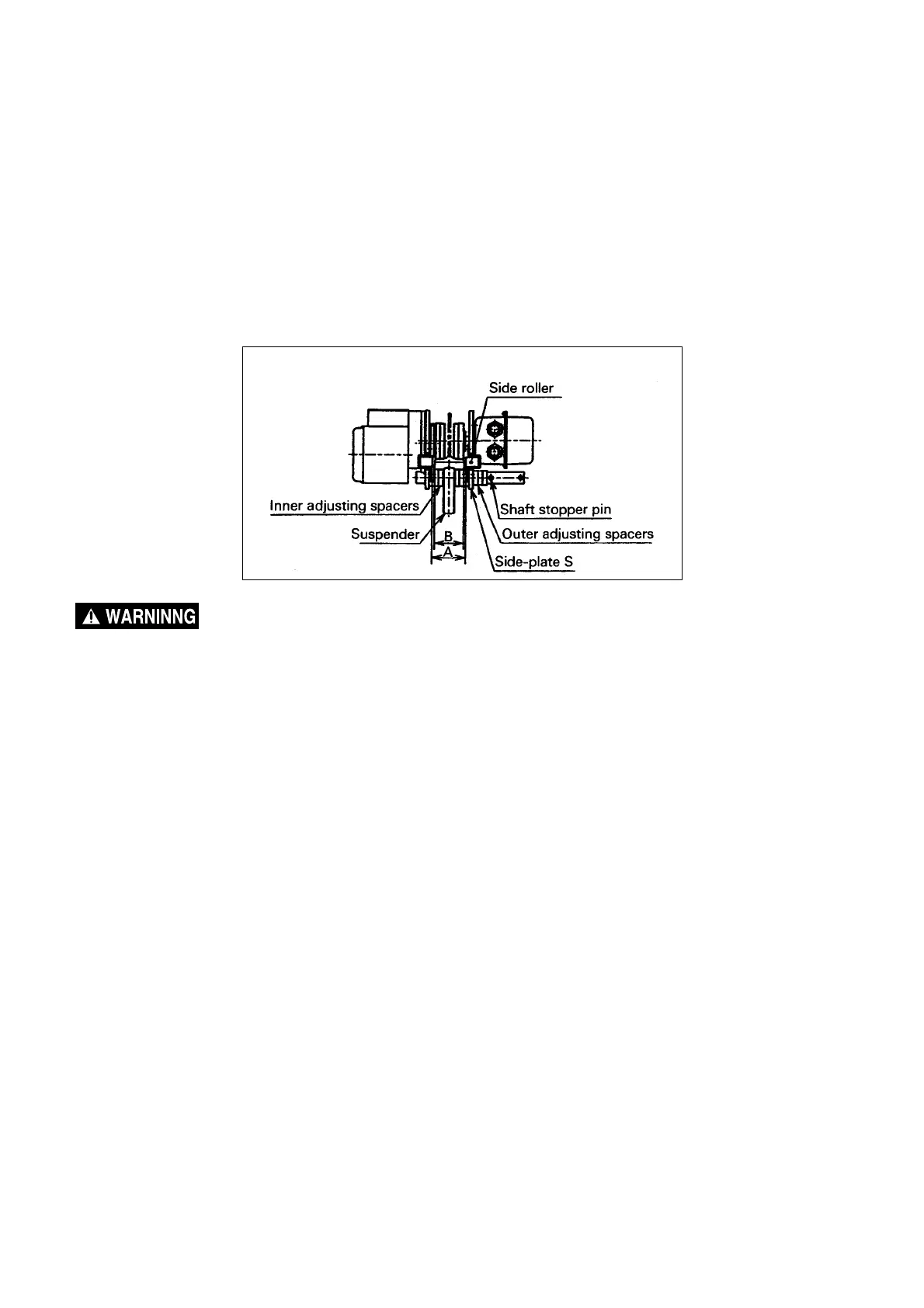
(b) Adjusting trolley width
Adjust the trolley width for the following proper clearance referring to Fig.5-8.
The proper "A" dimension is measured when both side plates are spread fully outward.
The "A" dimension is :
Rail flange width (B) + 4 mm approximately
If necessary to obtain the above "A" dimension, increase or decrease the number of adjusting spacers
irrespective of the quantities in Table 5-2.
After obtaining the proper "A" dimension, insert the split pin into the shaft stopper pin and securely bend
both branches of the split pin.
− 20 −
Fig.5-8 Adjusting trolley width
 Loading...