Do you have a question about the Klaxon Twist and is the answer not in the manual?
Lists the necessary tools for installing the Klaxon Linking System.
Advises installation by qualified personnel on flat surfaces.
Determine tube diameter and consult catalogue for correct product code.
Verify correct tyre and wheelchair wheel inflation pressure.
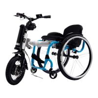
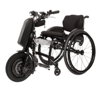
Identifies key components of the Twist device: Multi-Link Klaxon, Pin Bracket, Kickstand base.
Describes the upper and lower pin bracket on the Twist device.
Shows exploded and installed views of the linking system components.
Details the components of the connector: Mounting System, Lock/Unlock Lever, Front Hook.
Explains the linking/unlinking lever, safety button, and pin seats.
Provides a detailed view of the upper and lower parts of the pin seat.
Describes the central crossbeam's function and attachment mechanism.
Details clamping rings and provides a table of sizes and compatible coupling cuffs.
Advises keeping the batch code visible on the crossbeam for quick reference.
Instructs to insert the two fixing clamps into the front part of the crossbeam.
Explains how to align the fixing clamps to the grooved seat and gently tighten screws.
Ensure supplied items are suitable for the wheelchair before starting installation.
Temporarily remove seat/parts to identify and position clamping rings on the frame.
Install clamping rings on the frame, orienting screws correctly for upper/lower tubes.
Check compatibility and positioning of clamping rings relative to other components.
Caution for converging frames; use a level for accurate perpendicular alignment.
Secure one ring, insert crossbeam, fix with pin, align second ring for free movement.
Details vertical alignment for oval, converging, and parallel frames.
Verify user needs, ensure crossbeam removal, and check centering/parallelism.
Lightly tighten fixing clamps' screws to maintain their position.
Tighten clamping ring screws to 10Nm with copper grease, ensuring alignment.
Ensure the crossbeam is centered and parallel to the ground.
Adjust crossbeam position centrally with tolerance ± 0.5 mm and tighten screws.
Reassemble parts removed earlier (brakes, seat supports) to their correct positions.
Insert the Connector into the Crossbeam, ensuring free rotation for adjustment.
Provisionally tighten Front Hook screws to eliminate all backlashes.
Place Twist on ground, bring wheelchair closer until upper pin rests on Front Hook seat.
Lightly tighten fixing clamps' screws to maintain the upper pin's position.
Lift Linking Lever; check for green sign indicating safe and correct linking.
Push wheelchair wheels forward to establish complete linking and lift front castors.
Check distance between Twist and footrest to ensure no contact during rotation.
If necessary, extend the Connector by loosening screws and adjusting to user's need.
If the Connector is too long, cut the excess part of the smaller oval to size.
Apply copper grease and tighten the two fixing screws to 10 Nm.
Adjust steering set-up by checking angle relative to ground; recommends 2-6 degrees.
0° inclination: neutral steering, suitable for low speeds, lifts front castors.
Up to 6° inclination: more directionality, harder steering, lifts front castors minimally.
Mounting at 5° or 6° is suitable for riding with the handlebar installed.
Inclination below 0° causes instability and is incompatible with correct usage.
Once correct position is found, definitively tighten the 4 fixing screws to 10 Nm.
Raise Unlinking Lever to disengage lower pin; Twist rests on stand, engaged to upper pin.
Press the red Safety Button to completely disengage the Twist from the Linking System.
Unscrew clamps, bring wheelchair closer, adjust connector inclination until upper pin rests on seat.
Tighten fixing clamps lightly to secure the connector's adjusted position.
User sits on wheelchair; check alignment and engage Front Hook by maneuvering.
Permanently tighten crossbeam securing screws to 25 Nm with copper grease.
Check all screws are tight; test linking/unlinking operations with user or similar weight.
Permanently fix crossbeam position using Spring Type Straight Pins.
Adjust strap, drill a 5mm hole into the crossbeam strap.
Insert Spring Type Straight Pins into drilled holes and fix with a hammer.
| Brand | Klaxon |
|---|---|
| Model | Twist |
| Category | Wheelchair |
| Language | English |