Adjustments and Calibration
Thermal calibration is not required . Minimum and maximum control points can be calibrated before or
after the thermostat has been installed.
Adjusting the thermostat:
1. Using 1/16" hex/key, turn the setscrews on each side of the unit clockwise until the cover loosens.
2. Verify 16 VDC between the “+” and “–” terminals.
3. Remove set point slider stops (HFO-0027) if necessary.
4. Measure “T (?)” to “–” for output voltage. See table (below) to determine correct terminal.
5. Maximum limits MUST be greater than minimum limits. If in doubt, turn Max. limit fully clockwise
(increase) before proceeding.
NOTE: Dials rotate approximately 200° (8:00-4:00). DO NOT force dial beyond stop.
6. Connect voltmeter to to the meter taps (Using HSO-5001):
a. The two holes on the right are for the min. and max.
b. Measure actual flow in left holes. Thermostat must be wired to controller for this option.
7. Always adjust the minimum first. Adjust set point to request minimum flow using the minimum dial:**
DA Cooling; Set point > Room Temp.
RA heating; Set point < Room Temp.
8. Adjust set point to request maximum flow using the max. dial:**
RA Heating; Set point > Room Temp.
DA Cooling; Set point < Room Temp.
** Note: Limits may be set at the CSP or the thermostat. If setting min/max limits at the thermostat,
CSP’s Min. dial must be turned fully CCW to “0” AND the Max. dial must be turned fully
CW to “100”. This ensures that the CSP will not effect the limits.
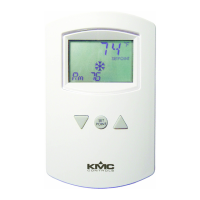
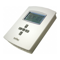
Thermostat
Terminal
5101 5102 5103/ 5105 5104 Description
V1 X X X Velocity input for read-out
T3 X X X Upper set-point output w/o limits
R1 X X X T1 override connect to "–" if unused
T1 X X X Upper set-point output w/limits
+ X X X X 16 VDC power supply input
12V X X X X 12 VDC power output
A X X X X Temperature averaging input
– X X X X Ground reference
T2 X X X Lower set-point output w/limits*
R2 X X X T2 override, connect to "–" if unused.*
*T4 X X Lower sett-point out w/o limits
V2 X X Velocity input for read-out
* Except 5104; T2 lower setpoint output is w/o limits. R2 is auxiliary limit trigger, voltage above 1
VDC @ R2 indexes T1 to the auxiliary flow limit
 Loading...