Do you have a question about the Knick Stratos Evo A402 and is the answer not in the manual?
Instructions for returning defective devices, including decontamination requirements.
Guidance on observing regulations for waste electrical and electronic equipment.
Safety instructions in official EU languages and others.
Installation and first steps, including operation, menu structure, and calibration.
Details on enclosure, mounting, connections, display, and general functions.
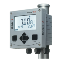
Lists available measurement functions like pH, ORP, Oxygen, and Conductivity.
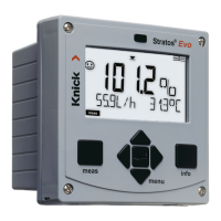
Description of display, color-coded interface, diagnostics, data logger, parameter sets, and password protection.
Details on control inputs, power supply, signal outputs, relay contacts, and PID controller.
Lists items that should be included in the device package.
Details on mounting plans, dimensions, accessories, and mounting types.
Explains how to connect analog sensors using interchangeable modules.
Details terminal suitability for wires and lists terminal assignments.
General instructions for device installation by trained experts.
Notes on observing control drawings for hazardous locations.
Instructions to connect the power supply to specific terminals.
Steps to connect a Memosens sensor and select the measuring function.
Selecting measurement procedure and changing function via Service menu.
Describes MemoSuite software for calibrating Memosens sensors.
Wiring details for standard and dual Memosens sensor connections.
Material, diameter, length, temperature, and ingress protection.
Lists cable types, lengths, and order numbers.
How analog sensor modules are inserted and recognized.
How to change the measuring function via the Service menu.
Details the Cond module for contacting conductivity measurement.
Wiring diagrams for various Cond sensor configurations.
Details the CondI module for inductive conductivity measurement.
Wiring diagrams for various CondI sensor configurations.
Details the module for dual conductivity measurement.
Wiring diagrams for dual conductivity sensor setups.
How to enter and operate the measuring mode.
Explanation of the functions of device keys for navigation and operation.
Overview of display elements and color-coded operating states.
Step-by-step guide to selecting an operating mode.
Step-by-step guide for entering numerical values.
Summary of functions available in Diagnostics, HOLD, Calibration, Configuration, and Service modes.
Explains LAST and FIX settings for output signals during HOLD.
How to activate HOLD mode externally and how to terminate it.
Explains error messages, blinking display, and alarm contacts.
Using the CONTROL input for flow measurement and alarm generation.
Configuration for sensor selection, current outputs, and compensation.
Configuration for control input, alarm modes, and relay outputs.
Details on configurable menu groups and external switching of parameter sets.
Table showing Cond sensor configuration options and defaults.
Device type recognition and sensor/range configuration.
Configuration of temperature units, detection, probe, and cleaning/sterilization cycles.
Configuration for sensor TAG and GROUP verification.
Table showing CondI sensor configuration options and defaults.
Device type recognition and sensor/range configuration.
Settings for measuring mode, concentration determination, and temperature unit.
Configuration for sensor TAG and GROUP verification.
Diagrams for sensor arrangement and overview of calculations (CALC).
Explains how dual conductivity measurement infers pH value.
Overview table for Cond sensor configuration parameters.
Overview table for CondI sensor configuration parameters.
Detailed configuration parameters for current outputs 1 and 2.
Configuration settings for control input, alarm, relays, USP, and PID controller.
Steps to configure current output range, start, and end values.
Selecting output characteristics (LIN, biLIN, LOG) and filter settings.
Configuring output current for error messages and HOLD mode.
Steps to select the temperature compensation method.
Details on compensation options and entering reference temperature.
Steps to select parameter sets via external signal.
Steps to configure control input for flow measurement.
Setup for alarm delay, Sensocheck, and Tempcheck.
Configuring alarms related to control input and flow monitoring.
Steps to configure limit function parameters for Relay 1.
Steps to configure limit function parameters for Relay 2.
Guidelines for protecting relay contacts from electrical erosion.
Typical applications and controller characteristic diagrams.
Presents controller equations and explains pulse controllers and HOLD behavior.
Steps to configure controller type, setpoint, and action components.
Adjusting neutral zone and action components (P, I, D).
Steps to configure WASH contact for rinsing or signaling parameter sets.
Steps to configure time, date, and measuring point (TAG/GROUP).
Details on sensor verification using TAG/GROUP for Memosens sensors.
Lists calibration modes for different sensor types.
Procedures for calibrating with solutions, product sampling, and zero calibration.
Calibrating by inputting cell factor and adjusting the temperature probe.
How to switch to measuring mode and view different displays.
How to select and set the main display.
Explains the meaning of different display colors for operating states.
Steps to activate and select diagnostics options.
Performing display, RAM, EEPROM, FLASH, and module tests.
Navigating and viewing logbook entries and audit trails.
Viewing measured values, sensor monitor data, and device version info.
Steps to activate Service mode and enter the passcode.
Viewing measured values and adjusting output voltage.
Managing passcodes, resetting to factory settings, and releasing options.
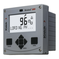
Procedure to recover from errors caused by power disruption during loading.
Common error codes related to sensors and measurement ranges.
Common error codes related to output signals and flow measurements.
Common error codes for system, module, and configuration issues.
Details on various Sensoface messages and their meanings.
Explanation of sensor monitoring and Sensoface indicators.
Monitoring ion exchanger capacity for Cond-Cond devices.
Lists device models, interchangeable modules, and TAN options.
Detailed specifications for the Cond device type.
Detailed specifications for the CondI device type.
Specifications for inputs, outputs, and relay contacts.
PID controller specifications and other general device parameters.
Specifications for display, keypad, communication, and electrical safety.
Specifications for operating conditions, housing, and connections.
Tables of conductivity values for KCl and NaCl solutions.
Graphs showing concentration vs. conductivity and temperature.
| Brand | Knick |
|---|---|
| Model | Stratos Evo A402 |
| Category | Measuring Instruments |
| Language | English |