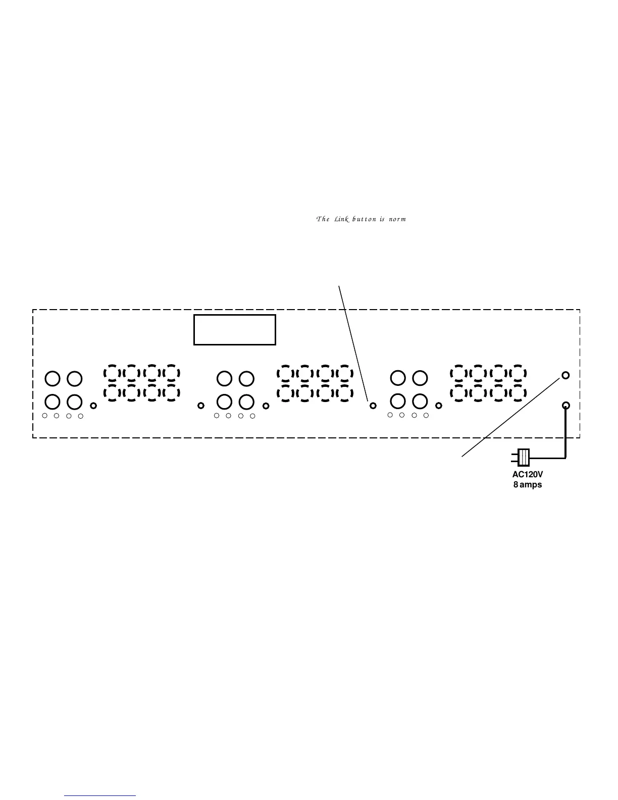
MR1250a/f Rear Panel
12V trigger
3
4
L
R
3L+
3L 3R 4L 4R
Gain
Inputs
Outputs
3L-
4L-
4L+
3R+
3R-
4R- 4R+
1
2
L
R
1L+
1L 1R 2L 2R
Gain
Inputs
Outputs
1L- 2L- 2L+
1R+
1R-
2R- 2R+
5
6
L
R
5L+
5L 5R 6L 6R
Gain
Inputs
Outputs
5L-
6L- 6L+
5R+
5R-
6R- 6R+
Link-Out
Link-Out
Link-Out
Link-Out
Link-Out
Link (out position)
cascades channel 1
to channels 2-6
Note 1: Ideal speaker impedance
is 8 ohms. When using 4 ohm
speakers, MR1250f with fan may
be needed to obtain full power
with out distortion caused by
protection system.
Caution: NEVER connect the
MR1250a or MR1250f to
impedances less than 4 ohms or
amplifier damage not covered by
the warranty may occur.
Trigger is 12 VDC (35mA per MR1250a
and/or MR1250f) via 3.5mm mono jack.
5 VDC trigger outputs will not work.
To connect the trigger to a receiver use a
12 VDC power supply (we suggest Knöll
PS1202 power supply). Plug the power
supply into the switched outlet on the
rear of the receiver. Connect the 12 volt
wire to a 3.5mm mono jack. Plug the jack
into the rear of the MR1250a or
MR1250f. 12 VDC polarity is not
important.
When the receiver is switched on, the
MR1250 amplifier is switched on.
AC120V
8 amps
The Link button is normally set to the in position to
give all six stereo inputs individual sources. When the
Link button is set to the out position, that input Left/
Right is linked or cascaded to input #1 (without the use
of Y cords). Any or all combination of linked inputs 2
to inputs 6 are possible. When all inputs are linked to
input 1 the input impedance is about 4000 ohms.
 Loading...