Do you have a question about the Koden CVS-118Mk II and is the answer not in the manual?
Instructions for safe handling and transfer of the manual.
Explanation of safety symbols used in the manual.
Procedures for safe installation by service personnel, covering mounting, materials, and environment.
Safety precautions for internal inspection by maintenance personnel, including capacitor discharge and power checks.
Guidelines for proper operation and system maintenance, including data backup and transducer care.
Explanation of the echo sounder's ultrasonic signal transmission and reception principle.
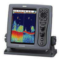
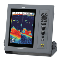
Details of data sets shown on the screen, including time marker, frequency, and depth.
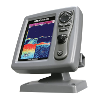
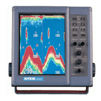
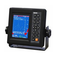
Identifies front panel components including LCD, knob, and control panel.
Shows rear panel connectors for SER DATA, TRI, STD, and power input.
Explains fixed and auto range display modes and initial setup steps.
Adjusts high and low frequency gain independently or automatically.
Sets the image feed rate for the display, from fastest to slowest.
Configures the automatic shifting of the image to follow the sea bottom.
Cycles through normal, bottom zoom, and other display formats.
Enables selection between bottom lock/discrimination and split screen layouts.
Explains partial and bottom zoom for enlarged image views.
Adjusts the magnification level for zoomed image sections.
Adjusts the starting point of the zoomed area relative to the normal screen.
Enables or disables the A-scope display for target identification.
Measures target depth by moving the VRM cursor on the screen.
Details how to store boat position, depth, and water temperature data.
Explains the limitation of one set of data and how to overwrite it.
Overview of menu screens, how to access them, and key functions.
Details operations like unit selection, bottom zoom, and language settings.
Adjusts split screen orientation and peak hold function.
Configures display language and enables simulation mode.
Covers sonic velocity correction, data sources, and gain types.
Controls panel illumination and enlarged character display features.
Manages interference rejection and white line display for clarity.
Adjusts color tones and background for optimal image viewing.
Sets alarms for bottom or fish presence, including depth limits and signal criteria.
Configures alarms for bottom detection and fish presence with depth limits.
Covers stopping/canceling alarms and usage precautions.
Adjusts auto gain and displays boat position from interfaced navigators.
Configures units for speed/temperature and enables water temp graph.
Resets trip mileage and clears stored event data.
Provides guidance for installation, gain, brightness, and data indication problems.
Lists key technical details including display, frequency, depth, and power consumption.
Lists included items like the display unit, cables, and manuals.
Details optional accessories like transducers and temp/speed sensors.
Instructions for securely mounting the display unit on a surface.
Details pin configurations for power, SER DATA, TRI, and STD connectors.
Describes NMEA input data formats like GGA, GLL, GNS, GTD, and HDM.
Explains the data fields within GPS, geographic, and ship's heading sentences.
Details bit configuration, baud rate, output level, and included sentences.
Explains data fields for DBS and DBT sentences related to depth measurements.
| Frequency | 50/200 kHz |
|---|---|
| Power Output | 1 kW |
| Display Type | Color LCD |
| Power Supply | 12-24 VDC |
| Type | Echo Sounder |
| Resolution | 640 x 480 pixels |
| Operating Temperature | -15°C to +55°C |
| Power Consumption | 30 W |