Do you have a question about the Koden KAT-100 and is the answer not in the manual?
Details critical safety precautions for installation and operation of the transceiver to prevent hazards and ensure proper functioning.
Provides general information including position source, compass safe distance, product category, and disposal guidelines.
Lists transceiver hardware/software versions and tracks revisions made to the manual, including document numbers and dates.
Explains the Automatic Identification System (AIS), its purpose, and different types of AIS devices.
Describes the two categories of data transmitted by AIS devices: static (MMSI, name) and dynamic (position, speed).
Outlines licensing requirements for operating an AIS transceiver, typically linked to VHF radio licenses.
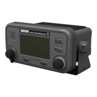
Describes the front panel layout of the KAT-100 transceiver, including buttons, scroll wheel, and display functions.
Explains that the transceiver is permanently powered and describes the startup sequence.
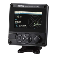
Introduces the six main operating screens accessible via the 'Screen' function key.
Describes the screen displaying other AIS-equipped vessels, their range, and bearing.
Presents information about the vessel on which the transceiver is installed, including MMSI, name, and destination.
Displays real-time dynamic data such as position, speed, course, and heading.
Shows received AIS text and Safety Related Messages (SRMs) and how to view their details.
Details the screen displaying active AIS system alarms, their status, and acknowledgment.
Shows the relative positions of other AIS targets on a radar-like display.
Covers receiving and sending AIS text messages and SRMs.
Explains how the transceiver detects and reports alarms, listing possible alarm conditions.
Describes the process of entering text and data using the scroll wheel and function keys.
Details how the transceiver handles long-range interrogations and replies.
Explains password protection for sensitive data and default password settings.
Introduces the main menu structure for accessing configuration settings like Voyage Data, Messages, User Settings, Installation, and Maintenance.
Describes the 1W transmission mode for tankers to comply with safety regulations.
Explains how to select nautical or metric units for speed and distance.
Details specific configuration requirements for operating in Inland AIS mode.
Lists and describes all items included with the KAT-100 AIS transceiver package.
Lists additional items required for installation, such as VHF antenna and cables.
Provides step-by-step instructions for installing the main components of the AIS system.
Details how to connect the transceiver, junction box, antennas, and other peripherals.
Guides the user through powering up and configuring the transceiver with vessel and voyage data.
Explains how to change the default password for security and access to settings.
Outlines steps to verify the transceiver is functioning correctly after installation and configuration.
Describes how to configure regional AIS channel and transmission settings.
Details specific configuration requirements for operating in Inland AIS mode.
Lists the international standards and regulations the AIS transceiver complies with.
Provides physical dimensions and weight for the transceiver and junction box.
Specifies operating temperature range, humidity, and water ingress protection rating.
Details power supply voltage, consumption, and current ratings.
Describes the display resolution, keypad, rotary control, and sounder specifications.
Lists specifications for the internal GPS receiver, including channels, time to fix, and accuracy.
Outlines specifications for the TDMA transmitter, including frequency range and output power.
Lists specifications for the TDMA receivers, including frequency range and sensitivity.
Provides specifications for the DSC receiver, including frequency, sensitivity, and modulation.
Details the types of RF connections and impedance for VHF and GPS antennas.
Lists specifications for sensor data input, bidirectional, differential correction, and RS232 ports.
Provides details of the connectors used for power and data interfaces.
Lists the IEC61162 sentences accepted and output by the transceiver's serial data ports.
Details the transmission intervals for various IEC61162 sentence types.
Shows the schematic for sensor data input ports and their termination options.
Describes the input and output circuitry for bi-directional data ports.
Specifies the output current and voltage capabilities of bi-directional ports.
Details the DGPS correction port and its reconfiguration options.
Describes the RS232 port for PC connection and charting applications.
Explains the format of input data sentences (IEC61162/NMEA 0183) and checksum calculation.
Provides detailed diagrams showing the physical dimensions of the AIS transceiver.
Shows diagrams illustrating the physical dimensions of the junction box.
Includes a drill drawing for dash mount bracket fixing holes.
Provides a drawing of the GPS antenna with its dimensions.
Lists ERI Ship types and their conversion to IMO ship types for AIS operation.
A form for recording essential vessel identification information post-installation.
Section for recording the dimensions and locations of internal and external GPS/GNSS antennas.
Table to note the model and AIS data port for connected equipment like GPS, Gyro, ECDIS.
A log for recording modifications and software updates made to the transceiver.
Fields for recording installer information, company, date, and vessel location.
| Brand | Koden |
|---|---|
| Model | KAT-100 |
| Category | Transceiver |
| Language | English |