TP-6836 4/14 53Section 7 Bypass/Isolation
7.6 Bypassing and Isolating,
1600- to 3000-Amp Switches
See Figure 7-8. Also see the notes after this procedure.
Hazardous voltage.
Will cause severe injury or death.
Only authorized personnel should
open the enclosure.
DANGER
Removing the transfer switch from bypass/isolation
models. Hazardous voltage can cause severe injury or
death. Bypass and isolate the transfer switch before removing
it from the enclosure. The bypass/isolation switch is
energized. Do not touch the isolation contact fingers or the
control circuit terminals.
1. Check that the ATS is in Automatic Mode:
a. The ATS is in the Auto position.
b. The manual bypass handle is in the Open
position.
c. The disconnect switch is in the Auto position.
2. Bypassing the ATS:
a. Turn the disconnect switch to the INHIBIT
position.
b. Position the bypass-selector switch to the
same power source as the ATS.
Note: The bypass switch uses safety interlocks to
prevent cross phasing.
c. Move the manual-bypass handle to the
BYPASS POSITION.
3. Testing the ATS:
a. Bypass the ATS as described in step 2.
b. Rotate the crank mechanism counterclockwise
until the ATS location pointer is aligned with
test; the ATS TEST position lamp will
illuminate.
c. Turn the disconnect switch to the AUTO
position.
d. Run a test as described in Section 6.5. End the
test before proceeding.
4. Isolating the ATS:
a. Bypass the ATS as described in step 2.
b. Rotate the crank mechanism counterclockwise
until the ATS location pointer is aligned with
isolate; the ATS ISOLATE position lamp will
illuminate.
1
2
3
4
5
7
6
566535
1. Bypass selector switch
2. Manual bypass handle BYPASS position
3. Manual bypass handle OPEN position
4. Corner Latches
5. Manual ATS handle
6. Crank mechanism
7. Disconnect s witch
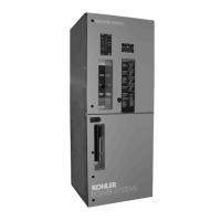
Figure 7-8 1600-3000 Amp Bypass Handle Positions

 Loading...