TP-6461 1/08 93Section 6, Component Replacement, Model KSS Switches
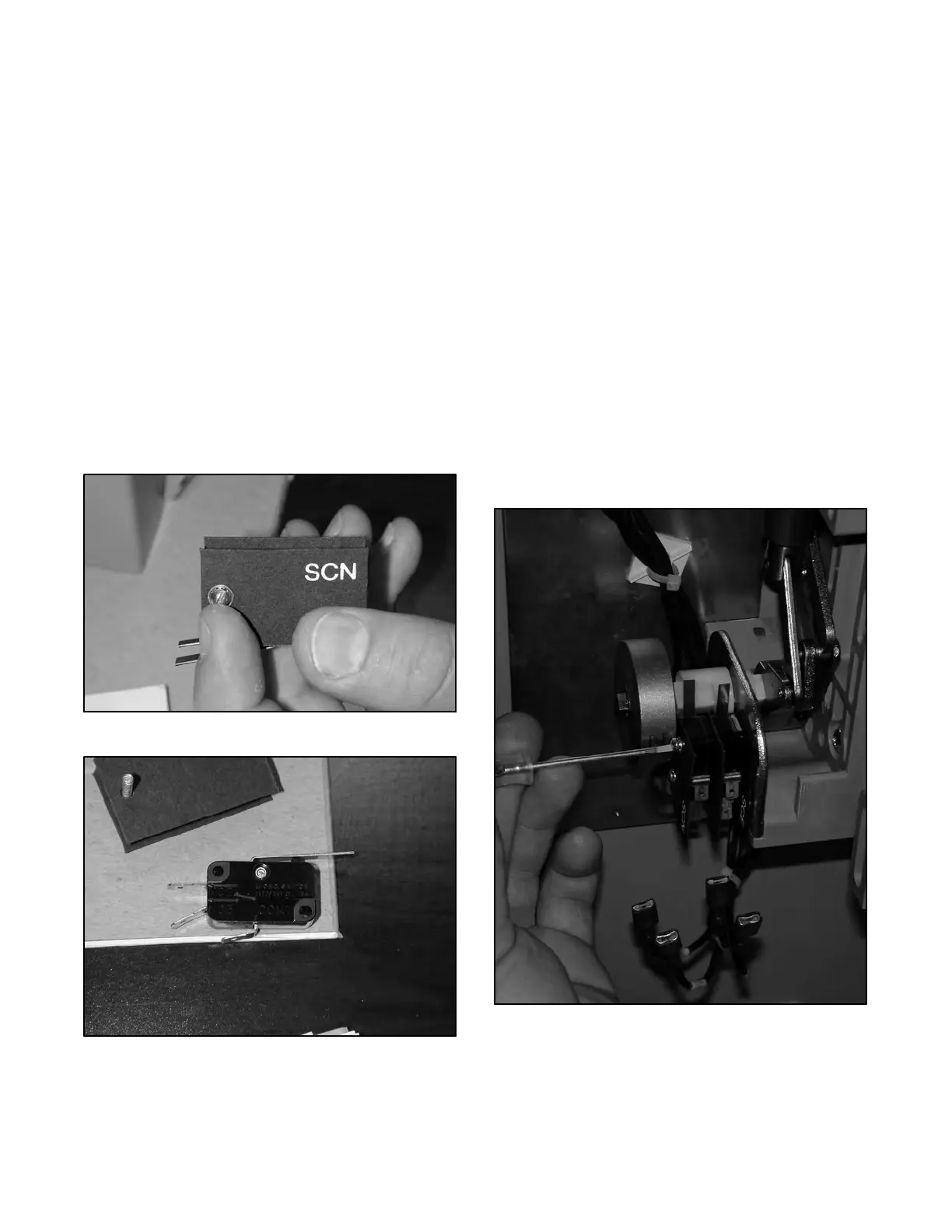
7. Remove the holding screws. Note the microswitch
labels on the insulators. See Figure 6-11.
8. Remove the microswitch assembly.
9. Remove the suspect microswitch. See
Figure 6-12.
10. Install the new microswitch into the assembly.
Note: Replace SCN/SCE insulators in the correct
order. Normally, the SCE is closest to the
base.
11. Reinstall the microswitch assembly. See
Figure 6-13.
a. Install the holding screws.
b. Tighten the holding screws.
c. Connect the fast-on connections to the
microswitch terminals as noted in step 5.
Figure 6-11 Microswitch Insulator with Label
Figure 6-12 Microswitch
12. Clean the inside of the ATS.
13. Close and lock the enclosure.
14. Connect power to the ATS.
15. Enable the generator set startup.
a. Check that the generator set master switch is in
the OFF position.
b. Reconnect the generator set engine starting
batter(ies), negative (--) lead last.
c. Reconnect the battery charger, if equipped.
16. Move the generator set master switch to the AUTO
position.
17. Test the transfer switch operation by performing
the Automatic Operation Test Procedure described
in Section 4.5.4.
Note: Do not leave the transfer switch in the Test
mode.
Figure 6-13 Microswitch Installation

 Loading...


