12-2
95-2 SERIES
TESTING AND ADJUSTING ADJUSTING VALVE CLEARANCE
ADJUSTING VALVE
CLEARANCE
1. Remove cylinder head cover.
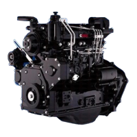
2. Rotate the crankshaft in the normal direction.
While watching the movement of the intake valve
of No. 4 cylinder, bring the No. 1 cylinder into
Compression Top Dead Center position and
align the TOP engraved mark on crankshaft
pulley (5) with pointer (6).
fl When the No. 1 cylinder comes near Com-
pression Top Dead Center position, the No.
4 intake valve will start to move (open).
3. Adjust the valve clearance for valves marked ‡
in the valve arrangement chart.
4. Rotate the crankshaft in the normal direction by
one revolution and adjust the valve clearance
for the remaining valves marked ‡.
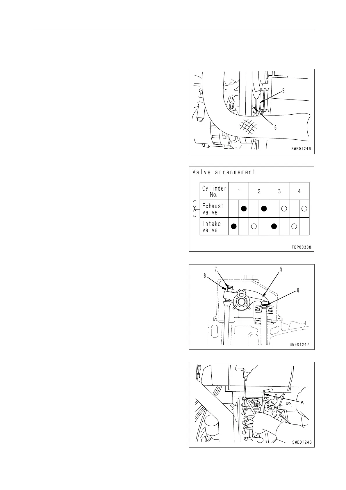
fl To adjust the valve clearance, loosen lock
nut (8) on adjustment screw (7), insert feeler
gauge A corresponding to the specified clear-
ance between valve stem (6) and rocker arm
(5), and adjust the clearance with the adjust-
ment screw until the thickness gauge can
slide lightly.
5. After the clearance is properly adjusted, tighten
the lock nut to secure the adjustment screw.
3 Lock nut: 44 ± 5.0 Nm {4.5 ± 0.5 kgm}
 Loading...