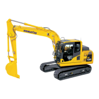
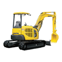
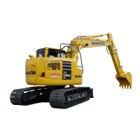
Do you have a question about the Komatsu PC128US-8 and is the answer not in the manual?
General information and important safety notices for machine operation and repair.
Crucial safety precautions to prevent injury during operation and maintenance.
Guide to understanding the structure and content of the shop manual.
Definitions of terms related to maintenance standards and part specifications.
Proper procedures for handling electrical and hydraulic parts to ensure longevity.
Specific instructions for connecting and disconnecting engine connectors to prevent damage.
Explains the coding system for electric wires used in circuit diagrams.
Essential safety measures and procedures for operating and handling machine units.
Step-by-step guide for safely disconnecting and connecting hydraulic couplers.
Table specifying correct tightening torques for various components during assembly.
Reference table for converting units used in the manual.
Overall technical specifications and data for the machine.
Detailed dimension drawings of the machine's components.
Illustrates the operational working range of the machine's equipment.
General specifications and performance characteristics of the machine.
Lists the weight of various parts and components of the machine.
Details the types and capacities of fuel, coolant, and lubricants required.
Details the engine's structure, function, and cooling system.
Describes the Power Take-Off (PTO) system's structure and function.
Explains the structure and function of the machine's cooling system.
Details the structure and function of the power train components.
Explains the structure and function of the swing circle mechanism.
Details the structure and function of the swing machinery.
Covers the structure and function of the undercarriage and frame.
Describes the structure and function of the track frame.
Explains the structure and function of the idler cushion.
Details the structure and function of the idler.
Explains the structure and function of the track roller.
Details the structure and function of the carrier roller.
Explains the structure and function of the sprocket.
Details the structure and function of the track shoe.
Covers the structure and function of the hydraulic system.
Diagram showing the layout of hydraulic equipment.
Explains the structure and function of valve controls.
Details the structure and function of the hydraulic tank and filter.
Explains the structure and function of the hydraulic pump.
Details the structure and function of the control valve.
Explains the structure and function of the CLSS system.
Describes the functions and operation of various valves.
Details the structure and function of the PPC valve.
Explains the structure and function of the swing motor.
Details the structure and function of the travel motor.
Provides standard service values for judging part condition.
Lists standard values for engine components.
Lists standard values for chassis components.
General information and considerations for testing and adjusting procedures.
Lists necessary tools for performing testing, adjusting, and troubleshooting.
Illustrations of special tools required for specific tasks.
Testing and adjusting procedures for the engine and cooling system.
Procedure for measuring and adjusting engine speed.
Method for testing exhaust gas temperature.
Procedure for analyzing exhaust gas color for diagnostics.
Instructions for adjusting valve clearance.
Method for testing cylinder compression pressure.
Procedure for measuring blow-by pressure in the engine.
Method for testing engine oil pressure.
Precautions and procedures for handling fuel system components.
Procedure for safely releasing residual pressure in the fuel system.
Method for testing fuel system pressure.
Procedures for testing fuel return rate and checking for leaks.
Method for inspecting the fuel circuit for leaks.
Procedure for testing and adjusting alternator belt tension.
Procedure for checking and adjusting AC compressor belt tension.
Testing and adjusting procedures for the power train system.
Method for testing swing circle bearing clearance.
Testing and adjusting procedures for undercarriage and frame.
Procedure for checking and adjusting track shoe tension.
Testing and adjusting procedures for the hydraulic system.
Testing oil pressure in work equipment, swing, and travel circuits.
Method for testing basic control circuit pressure.
Testing and adjusting oil pressure for PC control circuit.
Testing and adjusting oil pressure for LS control circuit.
Procedure for testing solenoid valve output pressure.
Procedure for testing PPC valve output pressure.
Method for adjusting play in work equipment and swing PPC valves.
Identifying parts causing hydraulic drift in work equipment.
Procedure for testing and adjusting travel deviation.
General information and guidelines for troubleshooting.
Key points to consider before and during troubleshooting.
Systematic approach to diagnosing and resolving issues.
Preliminary checks to perform prior to detailed troubleshooting.
Categorization of problems and their resolution procedures.
Explanation of how to interpret and use troubleshooting tables.
Common symptoms and their corresponding troubleshooting section numbers.
Reference table for electrical connector pin configurations.
List of T-boxes and T-adapters used in troubleshooting.
Diagrams indicating the location of fuses.
Diagnostic procedures based on specific failure codes.
Troubleshooting guide for electrical system issues.
Troubleshooting guide for hydraulic and mechanical systems.
Troubleshooting guide for engine related problems.
Overview and general precautions for disassembly and assembly tasks.
Instructions on how to effectively use this section of the manual.
List of coating materials used during assembly.
List of special tools required for disassembly and assembly.
Illustrations of special tools for disassembly and assembly.
Procedures for disassembly and assembly of the engine and cooling system.
Steps for removing and installing the fuel supply pump assembly.
Steps for removing and installing the fuel injector assembly.
Procedure for removing and installing the front oil seal.
Procedure for removing and installing the rear oil seal.
Steps for removing and installing the cylinder head assembly.
Procedure for removing and installing the radiator assembly.
Steps for removing and installing the aftercooler assembly.
Procedure for removing and installing the work equipment oil cooler.
Steps for removing and installing engine and work equipment pumps.
Procedure for removing and installing the fuel tank assembly.
Disassembly and assembly procedures for the power train system.
Steps for removing and installing travel motor and final drive.
Detailed disassembly and assembly of travel motor and final drive.
Steps for removing and installing swing motor and machinery.
Detailed disassembly and assembly of swing motor and machinery.
Procedure for removing and installing the swing circle assembly.
Disassembly and assembly procedures for undercarriage and frame.
Steps for disassembling and assembling track rollers.
Steps for disassembling and assembling the idler assembly.
Procedure for disassembling and assembling the recoil spring.
Procedure for spreading and installing track shoe assemblies.
Steps for removing and installing the sprocket.
Procedure for removing and installing the revolving frame assembly.
Steps for removing/installing counterweight without add-on weight.
Steps for removing/installing counterweight with add-on weight.
Disassembly and assembly procedures for the hydraulic system.
Steps for removing and installing the center swivel joint.
Detailed disassembly and assembly of the center swivel joint.
Procedure for removing and installing the hydraulic tank.
Steps for removing and installing the hydraulic pump.
Procedure for removing and installing the control valve assembly.
Detailed disassembly and assembly of the control valve.
Detailed disassembly and assembly of work equipment PPC valve.
Detailed disassembly and assembly of travel PPC valve.
Detailed disassembly and assembly of hydraulic cylinders.
Disassembly and assembly procedures for work equipment.
Steps for removing and installing the entire work equipment assembly.
Disassembly and assembly procedures for the cab and its attachments.
Steps for removing and installing the operator's cab assembly.
Procedure for removing and installing the cab door.
Procedure for removing and installing cab glass.
Steps for removing and installing the front window assembly.
Procedure for removing and installing the floor frame assembly.
Disassembly and assembly procedures for the electrical system.
Steps for removing and installing the air compressor.
Procedure for removing and installing the AC condenser.
Steps for removing and installing the AC unit assembly.
Procedure for removing and installing the machine monitor assembly.
Steps for removing and installing the pump controller assembly.
Steps for removing and installing the engine controller assembly.
Procedure for removing and installing the KOMTRAX module.
Collection of hydraulic diagrams and related drawings.
Explanation of symbols used in hydraulic circuit diagrams.
Detailed hydraulic circuit diagrams.
Collection of electrical diagrams and related drawings.
Explanation of symbols used in electrical circuit diagrams.
Detailed electrical circuit diagrams.
Table and drawing detailing electrical connector layouts.
| Brand | Komatsu |
|---|---|
| Model | PC128US-8 |
| Category | Excavators |
| Language | English |


