3.1 Connect the PWR1 / PWR2, and the unit will be powered on. PWR1 / PWR2 LED will
turn Blinking to show unit booting up. When the unit is ready, the PWR1 / PWR2 LED turn
Green to show current input.
3.2 Connect the 10/100M Ethernet Port: Connect the network nodes to the JetNet series with
4-pair CAT5 UTP cable. The 10/100M interfaces support auto MDI/MDIX.
3.3 Connect the 100Mbps(JetNet 4510(f)/4010) /Gigabit (JetNet 5010G/3010G) TX of combo
ports: Connect the network node to the JetNet series with 4-pair CAT5 UTP cable. The
100Mbps / Gigabit TX interfaces support auto MDI/MDIX as well.
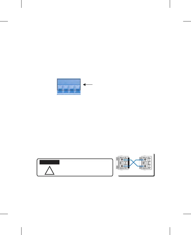
3.4 Connect the SFP transceiver: Plug in SFP ber transceiver. We recommend using
Korenix certicated SFP mini GBIC transceiver. Cross-connect the transmit channel at each
end to the receive channel at the opposite end as illustrated in the gure below.
V+ V- V+ V-
Power1 Power2
Accept 12~24AWG wire. The switch
provides auto polarity reverse
Power the unit and connect to network
Grounding JetNet
There is one grounding screw on the bottom side of JetNet Switch. Connect the frame
grounding of JetNet Switch to the grounding surface to ensure safety and prevent noise.
!
This is a Class 1 Laser/LED product.
Don’t stare at the Laser/LED Beam.
TX
RX
A B
TX
RX
ATTENTION
 Loading...