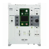
5. TIME Rotary Encoder Check
0. The check comes to this check the segments display is like fig.1
1. Set the pointer of the encoder knob to the reference position of bottom,
push the Encoder knob and reset the count to "0"
2. Rotate the encoder to the right for one around and confirm that the display is "30"
Confirm that the dot of the right bottom of the display turned ON. (Fig.2)
4. Rotate the encoder to the left for one around and confirm that the display is "-30"
Confirm that the dot of the right bottom of the display turned ON. (Fig.
Press the [TAP] to proceed to the next.
5. A/D (volume) Check (ch.1-4)
About the 1-4ch. each volume, do the check as the following order.
onfirm that you can move the volumes smoothly.
8 points' clicks, click positions are
Confirm that the segments display is like Fig.4.
1) Set the volume to the position of "8".
2) "7" is displayed in the segments LED, then set the volume to the position of "7".
3) "4" is displayed in the segments LED, then set the volume to the position of "4".
4) "2" is displayed in the segments LED, then set the volume to the position of "2".
5) "1" is displayed in the segments LED, then set the volume to the position of "1"
he segments LED becomes Fig.5, the proceed to the next.
0) Confirm that the segments LED is Fig.5.
The segments LED becomes Fig.6, the proceed to the next.
3.<GAIN> → 4.<PAN> → 5.<HI> → 6.<MID> → 7.<LO>
0) Confirm that the segments display are Fig.6-10(see right) .
1) Rotate the volume to MAX (right end).
2) After the color of the <GAIN> changed, rotate the volume to MIN (left end).
After the color of the <GAIN> changed, rotate the volume to the center position.
he segments display changed Fig.7-11, then proceed to the next.
8.<TIME> → 9.<MOD> → 10.<FB> → 11.<FX MIX>
(0) Confirm that the segments LED is Fig.
1) Rotate the volume to MAX (right end).
2) Delay LED is blinking, then rotate the volume to the MIN (left end).
he segments display changed Fig.12-15, then proceed to the next.
0) Confirm that the segments LED is Fig.15.
1) Set the CH FADER to MAX (top). Confirm that the meter LEDs beside the fader are
lighting corresponding to the position of the fader.
set the CH FADER to MIN (bottom).
nd the segments display changed to Fig.16, then proceed to the next channel.
KORG INC.
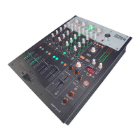
ZERO4 (X-5800) Check before Shipping
Revised
No.
Date 3/102007/4/23
QCI-5800 Page
 Loading...