Do you have a question about the Kracht AS 8 and is the answer not in the manual?
Describes the installation and operation of the Indicator AS 8.
Provides the contact details for KRACHT GmbH.
Explains hazard symbols DANGER and WARNING.
Specifies the allowed applications and environments for the device.
States that staff must be qualified and familiar with instructions.
Lists general safety rules like cleanliness, PPE, and no modifications.
Details risks associated with exposed electrical components and malfunctions.
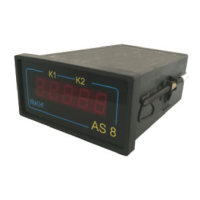
Explains how the AS 8 unit functions as a display and control device.
Describes different installation types and the wiring of the AS 8.
Explains the ordering system for the AS 8 based on its features.
Provides specifications like display type, dimensions, material, and protection class.
Details electrical specifications for processor, supply voltage, inputs, outputs, and interfaces.
Instructions for checking and handling the device during transport.
Specifies requirements for storing the device in a dry, dust-free environment.
Shows the pinout for screw terminals and explains their functions.
Explains how to set the supply voltage for 230 V AC.
Details terminal assignments for AC and DC supply voltages.
Explains how to connect sensor supply voltage and signal inputs.
Describes the terminal assignment for the two relay contacts.
Explains the terminal assignment for the analogue output.
Details terminal connections for printer interface.
Explains RS232 serial interface settings, baud rate, and data format.
Describes how to configure the AS 8 parameters using ASCII character strings via serial interface.
States the need to adapt the unit to the connected flow meter before start-up.
Explains the general procedure for entering values using buttons.
Details the initial step of pressing and holding F1 for four seconds.
Describes how to navigate and select menu code numbers using buttons.
Explains how to change input values and set decimal points.
Outlines the steps to finish input and reattach panels.
Explains how to configure the measured variable using dip switches and pulse volume.
Describes how to set the time basis (minute, hour, second) using dip switches.
Provides a table summarizing menu codes, standard settings, user values, and functions.
Lists pulse volume flow meter types and their corresponding input values for display.
Explains the "Maximum value analogue output" function and its settings.
Details setting filter values or gate times for frequency measurement.
Explains programming relay functions (make-contact, break-contact, window) for relays 1 and 2.
Describes functions for Relay 2, Relay 1, Analogue output, and Display selection.
Details functions for Analogue output, Error display, and Count input settings.
Provides warnings for working on electrical components and potential malfunctions during repair.
Covers troubleshooting, elimination of damage, and repairs by the manufacturer.
Lists common failures, potential causes, and suggested measures for troubleshooting.
| Brand | Kracht |
|---|---|
| Model | AS 8 |
| Category | Touch Panel |
| Language | English |