Do you have a question about the KROHNE OPTIWAVE 5400 C and is the answer not in the manual?
Details firmware revisions and their effect on compatibility.
Specifies how the device is designed to be used and its measurement capabilities.
Covers radio approvals for EU and US/Canada, including permitted antenna types.
Includes copyright, disclaimer, product liability, warranty, and documentation information.
Provides general safety warnings and instructions for safe operation.
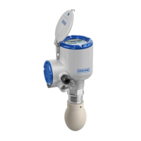
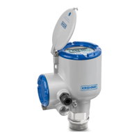
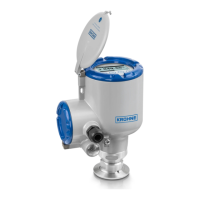
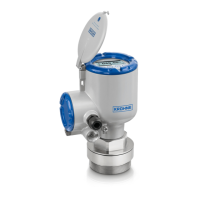
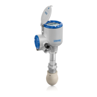
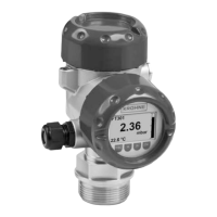
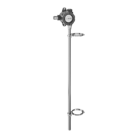
Describes the 24 GHz FMCW-radar level transmitter's technology and capabilities.
General precautions and checks before starting the installation process.
Provides guidance on the optimal placement of the device for accurate measurement.
Details limitations and considerations to avoid interference and ensure correct installation.
Critical safety warnings for all electrical connection work.
Explains how to connect the current output for Non-Ex and hazardous devices.
Points to check before energizing the device for the first time.
Steps to power up and begin operating the device.
Describes the different modes for operating the device: Normal and Program.
How to view measurement data and status messages in Normal mode.
How to change device settings, run diagnostics, and configure parameters.
Advanced configuration procedures including standard setup and spectrum recording.
Explains device status symbols and error messages based on NAMUR NE 107.
Comprehensive technical specifications of the device, including measuring system and design.
| Type | Radar Level Transmitter |
|---|---|
| Measurement Principle | FMCW (Frequency Modulated Continuous Wave) radar |
| Process Temperature | -40 to 200 °C (-40 to 392 °F) |
| Process Pressure | Up to 40 bar |
| Accuracy | ± 2 mm |
| Output Signal | 4-20 mA, HART |
| Enclosure Rating | IP66/IP67, Type 4X |
| Approvals | ATEX, IECEx, FM, CSA |
| Housing Material | Aluminum, stainless steel |
| Wetted Material | PTFE |
| Application | Liquids |
| Process connection | Flange, thread |