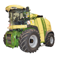
Maintenance – supply system
668
Fig. 601
• Connect the hose of the compressed air line blowing device (1).
• Connect plug of the RockProtect and CropControl (2) options.
• Connect the connection lines to the central lubrication (3), ensuring that the lines are
installed and attached correctly.
• Connect the connector cable to the chopping drum unit (4).
Fig. 602
NOTE
The connections of the hydraulic lines are located at front left, optionally a cylinder can be
installed for the pendulum frame, the connections (4) for this are located at front right.
The system must be depressurised when removing the hydraulic lines (3, 4).
• Disconnect the hydraulic lines (3, 4) on the hydraulic couplings and close off with dust caps.
• Remove the lighting cable plug (2) and the connection line plug of the front attachment
sensors (1) and close off with dust caps.
 Loading...