Start-up
48
Pos: 23.14 /Übersc hriften/Überschri ften 3/A-E/Anschluss der Hydraulikleitun gen @ 0\mod_1199777037794 _78.docx @ 34244 @ 3 @ 1
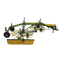
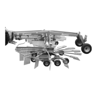
7.2.2 Connecting the hydraulic lines
Pos: 23.15 /BA/Inbetr iebnahme/Schwader /Hydraulikansch luss/Hydraulikansc hluss Swadro 1000 @ 2\mod_1202 916724602_78.doc x @ 62953 @ @ 1
SW1000005
1
2
SW1000021
Figure 23
The following control units are required on the tractor to operate the machine:
The machine requires a single-action control unit with unpressurised backflow on the tractor.
• Pressure line (1) ((red) nominal width 15)
• Return line (2) ((blue) nominal width 18)
• If necessary couple load-sensing pipe – nominal width 12 – (red dust cap) to the LS
connection of the tractor.
Pos: 23.16 /BA/Inbetr iebnahme/Ladewagen/ Hinweis Farbliche Kennz eichnung beachten @ 0\ mod_1199779285091_78. docx @ 34408 @ @ 1
Note
• Observe colour-coded signs on the tractor hydraulic system!
Pos: 23.17 /BA/W artung/Load-Sensing/SW 1000/Hinweis Load-Sen sing SW 1000 @ 3\mod_120524806 3072_78.docx @ 73574 @ @ 1
Note
• With closed (constant pressure or load-sensing) hydraulic system and connected load-
sensing line:
Before coupling, screw out the system screw (1) on the hydraulic block fully.
• With open (constant-current) hydraulic system and not connected load-sensing line:
The system screw (1) is preset in the factory. (The system screw (1) on the hydraulic block
must be screwed in up to the stop.)
Pos: 23.18 /BA/--- ------------ Seitenumbruch------ ---------- @ 0\mod_119617 5311226_0.doc x @ 4165 @ @ 1
 Loading...