4. Load the rotor parts elastically by means of slotted round nut 920 and disc
spring 950. For this purpose, compress disc spring 950 to blocking point and
then undo slotted round nut 920 again by half a turn (180°).
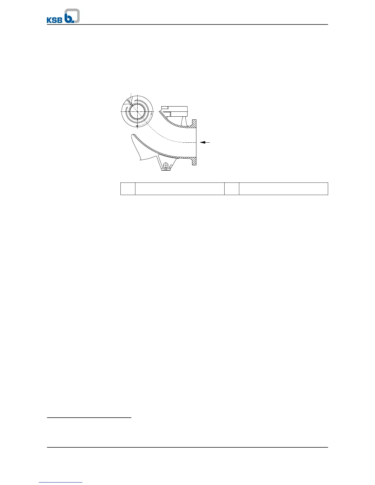
5. Position shaft seal housing 441 with the anti-vortex vanes pointing vertically
upwards. For shaft unit DW 90
17)
position shaft seal housing 441 with the anti-
vortex vanes at an angle of 45° off the horizontal, leading upwards as an
extension of the suction nozzle.
Fig. 31:
Position of the anti-vortex vane for shaft unit DW 90
a
Anti-vortex vane at the shaft seal
housing
b Suction nozzle
✓ The impeller has been fitted.
✓ The shaft seal has been fitted.
✓ The corresponding general assembly drawing and installation instructions are
available.
1. Fit non-drive end spacer sleeve 525 like shaft protecting sleeve 524.01.
2. Pull on shaft protecting sleeve 524.02 and mount bearing housing 350.02 with
fitted bearing bush 545 and O-ring 412.1.
3. Fasten shaft protecting sleeve 524.02 to the shaft with disc 550.03, disc spring
950 and nut 920.01.
4. Load the rotor parts elastically by means of slotted round nut 920 and disc
spring 950. For this purpose, compress disc spring 950 to blocking point. Then
undo slotted round nut 920 again by half a turn (180°).
5. Fit bearing cover 160.
6. Position shaft seal housing 441 with the anti-vortex vanes pointing vertically
upwards. For shaft unit DW 90
18)
position shaft seal housing 441 with the anti-
vortex vanes at an angle of 45° off the horizontal, leading upwards as an
extension of the suction nozzle.
Vertical installation with
plain bearing
17)
Applies to the following sizes only: Omega 250-800, 300-560, 300-700, 350-430 and 350-510
18)
Applies to the following sizes only: Omega 250-800, 300-560, 300-700, 350-430 and 350-510
7 Servicing/Maintenance
64 of 94
Omega / Omega V

 Loading...


