9
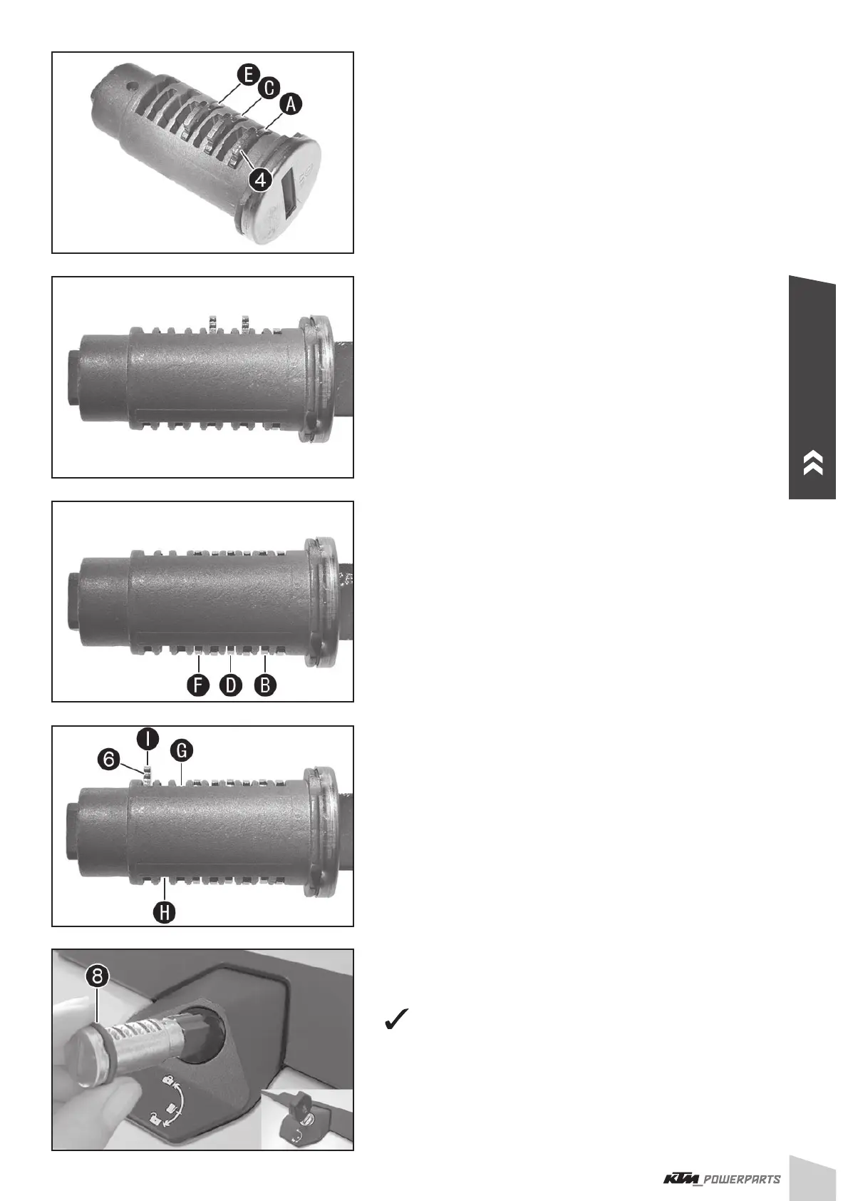
- Insert wafers with the number 1 into the chambers , and .
- Insert the key and check whether the wafers with the number 1 fi t.
- Replace wafers that do not fi t with wafers with the right number.
NOTE
The wafers should be aligned fl ush with the locking cylinder. The num-
ber of visible grooves indicates which wafer needs to be used. This
example shows a cylinder in which three wafers with number 1 have
been installed. Two grooves are visible on each of the two protruding
wafers. This means that wafers with number 3 need to be installed.
It is advisable to note down which numbers the matching wafers have
so that the other locking cylinders can be assembled in the same
manner.
- Repeat the steps for the slots
, and until the fi rst six slots
are occupied with the matching wafers.
- Insert spring
for the snap-in plate and then the snap-in plate
into slot .
NOTE
Slots
and remain empty.
- Mount O-ring
.
- Position locking cylinder as shown in the fi gure and insert with the
aid of the key (catch must face upward).
Snap-in plate
(: engages.
ENGLISH
 Loading...