6-13
– Use special tool 773.29.051.000 1 to press against the piston on
the chain tensioner all the way to the stop to release the assembly
lock and cause the piston to extend. This puts a physical load on the
chain tensioner rail and tensions the timing chain.
– Mount the screw on the chain tensioner again and tighten to 10
Nm.
NOTE: check by pressing against the chain tensioner rail; the chain
tensioner should lock, ensuring that the timing chain retains its tension
if the engine is started without sufficient oil pressure.
!
CAUTION
!
I
F THE CHAIN TENSIONER IS NOT LOCKED AS DESCRIBED IN CHAPTER 5 AND
RELIEVED AFTER MOUNTING
,
THE TIMING CHAIN WILL JUMP WHEN THE ENGINE IS
STARTED AND RESULT IN ENGINE DAMAGE
.
– Unscrew the engine locking screw 773.29.010.000, turn the
crankshaft 2 turns in a counterclockwise direction and screw the
engine locking screw back in again; make sure the engine is locked.
– Check the position of the camshaft gear: the mark on the camshaft
2 must be in alignment with the mark on the camshaft retaining
bracket.
NOTE: the mark on the camshaft retaining bracket points to the center
of the screw
3.
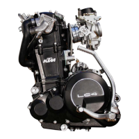
Right side of the engine
– Screw in the temperature sensor 4 (A/F 19 mm, tightening torque
12 Nm) and spark plug
5 (750.29.172.000, tightening torque 17
Nm).
2
3
4
5
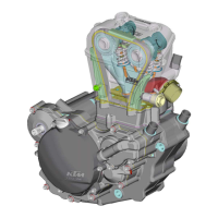
– Mount the centering sleeves and a new
clutch cover gasket.
– Mount the clutch cover.
– Mount the screws (see photo for
lengths) and tighten to 10 Nm.
M6x25
M6x25
M6x25
M6x35
M6x30
M6x25
M6x25
M6x25
M6x25
M6x25
M6x25
M6x30
1
 Loading...