11 Technical Data
11.1 General Data
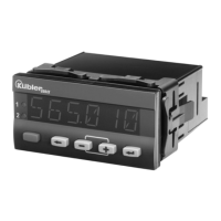
Display: 6-digit, 14 segment LED
Digit height: 14 mm
Data retention: > 10 years, EEPROM
O
peration: 5 keys
11.2 Measuring signal inputs
Sampling rate: 10 readings/sec
SELV circuits, reinforced / double insulation
Voltage input
Progr. ranges: 0 … 10 V, 2 … 10 V, ± 10 V
Meas. range: -10.5 ... +10.5 V
Resolution: < 0.4 mV (±15Bit)
Meas. accuracy typ. 0.02 % of range
@ 23°C: max. 0.05 % of range
Temperature drift: < 100 ppm/K
Input resistance: 1 M
Max. voltage: ± 30 V
Current input
Progr. ranges: 0 ... 20 mA, 4 … 20 mA
Measuring range: -0.5 ... 21 mA
Resolution: 1 µA (> 14 Bit)
Measuring accuracy typ. 0.02 % of range
@ 23°C: max. 0.05 % of range
Temperature drift: < 100 ppm/K
Input resistance: 22 + PTC 25
Voltage drop: ca. 1,8 V @ 20 mA
Max. current: 60 mA
11.3 Control Inputs MPI 1 / MPI 2
SELV circuits, reinforced / double insulation
Quantity: 2, optocouplers
Function: programmable
Switching levels: Low: < 2 V
High: > 4 V (max. 30 V)
Pulse length: >100 ms
11.4 Alarm outputs
Relays: changeover contacts
Prescribed fuse: 5A
Switching voltage: max. 250 V AC / 125 V DC
min. 5 V AC / V DC
Switching current: max. 5 A AC / A DC
min. 10 mA
Switching capacity: max. 1250 VA / 150 W
The maximum values shall in no case
be exceeded!
Mechanical service life (switching cycles) 1x10
7
N° of switching cycles at 5 A / 250 V AC 5x10
4
N° of switching cycles at 5 A /30 V DC 5x10
4
11.5 Supply voltage
AC supply: 100 ... 240 V AC / max. 9 VA
50 / 60 Hz, Tolerance ± 10%
ext. fuse protection: T 0.1 A
DC supply: 10 ... 30 VDC / max. 3.5 W
with galvanic isolation and,
reverse polarity protection
SELV, CLASS II (Limited
Power Source)
ext. fuse protection: T 0.4 A
Mains hum 50 Hz or 60 Hz,
suppression : programmable
11.6 Sensor Supply voltage
(Voltage output for external sensors)
SELV circuits, reinforced / double insulation
at AC supply: 24 VDC r15 %, 30 mA
15 VDC r1 %, 25 mA
at DC supply: 15 VDC r1 %, 25 mA
11.7 Climatic Conditions
Operating temperature: -20°C ... +65°C
Storage temperature: -25°C ... +75°C
Relative humidity: R.H. 93 % at +40°C,
non-condensing
Altitude: up to 2000 m
11.8 EMC
Noise immunity: EN61000-6-2
with shielded signal and
control cables
Noise emission: EN55011 Class B
11.9 Device Safety
Design to: EN 61010 Part 1
Protection Class: Protection Class 2 (front side)
Only the front side is classified as
accessible for the operator.
Application area: Pollution level 2
over-voltage Category II
Insulation: Front: double insulation,
Rear side: basic insulation,
Signal inputs and und sensor power supply: SELV
11.10 Mechanical Data
Housing: Panel mount housing
to DIN 43 700, RAL 7021
Dimensions: 96 x 48 x 102 mm
Panel cut-out: 92
+0.8
x 45
+0.6
mm
Installation depth: approx. 92 mm incl. terminals
Weight:: approx. 180 g
Protection: IP65 (front, device only)
Housing material: Polycarbonate UL94 V-2
Vibration resistance: 10 - 55 Hz / 1 mm / XYZ
EN60068-2-6 30 min in each direction
 Loading...