TRANSMISSION
B1220, B1620, B1820, WSM
3-S13
(EU)
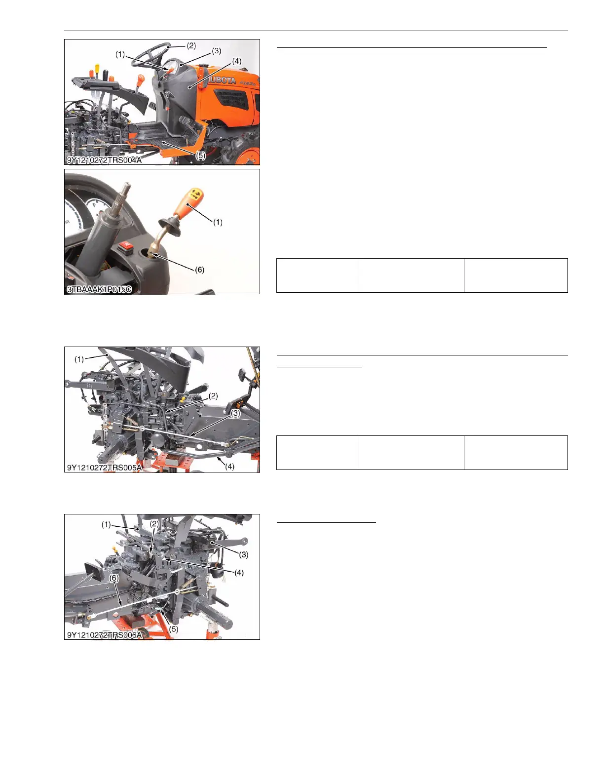
Steering Wheel, Meter Panel, Panel Under Cover and Step
1. Remove the steering wheel cap.
2. Remove the steering wheel mounting nut and remove the
steering wheel (2) with a steering wheel pillar (Code No.
07916-51090).
3. Tap out the spring pin (6) and remove the hand accelerator
lever (1).
4. Open the meter panel (3).
5. Disconnect the meter panel connector, combination switch
connector, hazard switch connector and hour meter cable. Then
remove the meter panel (3). [Except B1220]
6. Disconnect the meter panel connector and head light switch
connector. Then remove the meter panel. [Only B1220]
7. Disconnect the main switch connector and remove the panel
under cover (4).
8. Remove the rubber mat (5).
9. Disconnect the springs and parking brake rod, and then remove
the steps.
9Y1210272TRS0009US0
Delivery Pipe, Suction Pipe, Position Control Lever and Front
Wheel Drive Lever
1. Remove the brake rod, R.H. (3).
2. Disconnect the hydraulic control lever (1).
3. Remove the pipe clamps and disconnect the 3 Points hitch
delivery pipe (2) from hydraulic cylinder case.
4. Disconnect the suction pipe (4) at the transmission case side.
9Y1210272TRS0010US0
Seat Stay and Others
1. Disconnect the wire harness from the front seat stay and (1) and
remove the front seat stay (1) and rear seat stay (3).
2. Disconnect the main gear shift switch connector (2) and PTO
safety switch connector (4).
3. Disconnect the lead wires of brakes switch (5).
4. Remove the brake rod, L.H..
9Y1210272TRS0011US0
Tightening torque
Steering wheel mounting
nut
30 to 49 N·m
3.0 to 5.0 kgf·m
22 to 36 lbf·ft
(1) Accelerator Lever
(2) Steering Wheel
(3) Meter Panel
(4) Panel Under Cover
(5) Rubber Mat
(6) Spring Pin
Tightening torque
Joint bolt (3 Points hitch
delivery pipe)
50 to 60 N·m
5.1 to 6.1 kgf·m
37 to 44 lbf·ft
(1) Hydraulic Control Lever
(2) 3 Point Hitch Delivery Pipe
(3) Brake Rod, R.H.
(4) Suction Pipe
(1) Front Seat Stay
(2) Main Gear Shift Switch Connector
(3) Rear Seat Stay
(4) PTO Safety Switch Connector
(5) Lead Wire
(6) Brake Rod, L.H.

 Loading...