TRANSAXLE
G23, G26, WSM
2-S40
(EU)
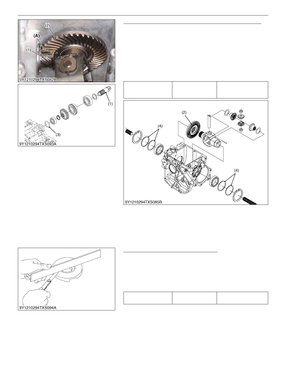
Backlash between Spiral Bevel Pinion Gear and Bevel Gear
1. Temporarily assemble the spiral bevel pinion gear (1) and the
bevel gear (2) in the transaxle case.
2. Prepare the fuse bent already three to four times.
3. Hold the fuse on the bevel gear teeth upper surface "A".
4. Turn the front drive shaft one turn clockwise by hands.
5. Measure the thickness of the fuse as a backlash between the
spiral bevel pinion gear and the bevel gear.
6. If the back lash exceeds the factory specifications, adjust the
shims (4).
9Y1210294TXS0044US0
(3) Brake Case
Flatness of Actuator and Bearing Holder
1. Place a straightedge of 150 mm (5.91 in.) or more in length on
the contacting surface of the actuator and the bearing holder.
2. Inspect the friction surface of the actuator and the bearing
holder with the straightedge, and determine if a 0.30 mm
(0.0118 in.) feeler gauge will fit on the part of wear.
3. If it will fit, resurface.
9Y1210294TXS0045US0
Backlash between spiral
bevel pinion and bevel
gear
Factory specification
0.10 to 0.30 mm
0.0040 to 0.011 in.
(1) Pinion Gear
(2) Bevel Gear
(3) Shim
(4) Shim
A : Bevel Gear Teeth Upper Surface
Flatness of actuator and
bearing holder
Allowable limit
0.30 mm
0.0118 in.
 Loading...