7-S7
L2800, L3400, WSM
STEERING
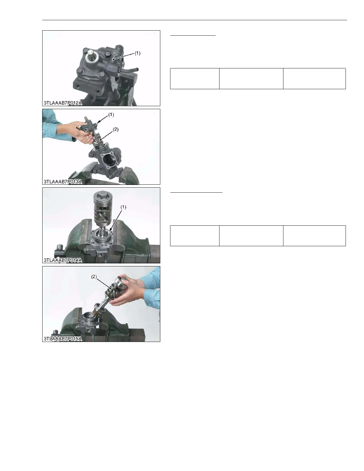
Valve Assembly
1. Remove the valve mounting screws.
2. Remove the valve assembly (1) and ball nut (2).
(When reassembling)
• Apply oil to O-ring and oil seal.
W10215140
Ball Nut Assembly
1. Remove the lock nut (1).
2. Take out the ball nut assembly (2).
(When reassembling)
• Apply oil to sleeve.
W10217200
Tightening torque Valve mounting screw
48.0 to 55.0 N·m
4.9 to 5.7 kgf·m
35.4 to 41.2 ft-lbs
(1) Valve Assembly (2) Ball Nut
Tightening torque Lock nut
88.3 to 107.9 N·m
9.0 to 11.1 kgf·m
65.1 to 80.3 ft-lbs
(1) Lock Nut (2) Ball Nut Assembly
Tractor Manuals Scotland - Please Do Not Copy

 Loading...


