Kurz Instruments, Inc. 831-646-5911
2411 Garden Road www.kurzinstruments.com
Monterey, CA 93940
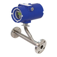
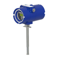
360208-F 454FTB, 504FTB, 534FTB 24
Fix32, etc. Please see the manual for more on OPC and the Modbus register assignments
for the MFT B-series product line.
To setup the digital output, the communication protocol needs to be specified along with
the baud rate and serial port type.
A. Protocols:
1. Remote Terminal Mode is where you talk to the meter from a Laptop/PC running
a terminal emulator program like TeraTerm.
2. Logging a meter summary to the USB port can be generated from an internal
timer. The data can be logged as a .csv file using TeraTerm (or any terminal
emulation program) and then loaded directly into a spreadsheet for viewing or
analyzing. Terminal echo should be turned OFF when capturing the logged data
so that the data written to the LCD display is not logged in the .csv file. The USB
logging can only be used for a single point (single flow meter) connection since
there is no device addressing scheme to differentiate between multiple flow
meters in the communication loop.
3. Modbus is a multi-point protocol that can be used on the RS-485 port. Both the
Modbus ASCII or RTU protocols are supported. The device address may be any
number between 1 and 247. Modbus TCP/IP requires a serial to Ethernet gateway
as the native interface in the flow meter is RS-485.
B. Baud Rate:
For USB data logging and remote terminal mode, the MFT B-Series only supports a baud
rate of 9600 bits/sec. For Modbus protocol, the MFT B-Series can support baud rates
from 9600 bits/sec to 57,600 bits/sec. This can be configured from the local keypad, the
remote terminal interface or through KzComm.
C. Serial Port Type:
USB is convenient for communicating between a single flow meter to a PC. If multiple
flow meters will be installed over a long distance between the PC, the RS-485 should be
used for communication. When using the RS-485 connection there are bus loading
resistors and other installation requirements that need to be addressed for reliable
operation. These are defined on the field wiring diagrams.
The USB interface requires a Driver to be
installed on the PC to emulate a COM port. The
USB driver that will be installed on the PC
depends on the serial connection used between
the PC and the flow meter. If the PC will
connect to the flow meter at the USB mini-b
connector on the meter’s SC board (as shown in