Attenuation Select
One
of the three channel amplitude control digital/analog
converter settings may be selected fqr each channel. These settings
are:
1.
RAMP the amplitude
DAC
output
2.
Maximum Attenuation
3.
Assign
to
Group
A
If RAMP the amplitude DAC output is chosen, the ouput signal
of the amplitude DAC may be observed with an oscilloscope at the
Channel board locations shown
in
Table
3.
If
maximum
attenuation
is selected the output of the amplitude DAC should be +10 VDC. If
minimum
attenuation is selected, the output of the amplitude DAC
for that channel should be
0
VDC.
Note:
If neither
RAM
P nor M A X 1M U M
attenuation
is
selected, the default
is
MINIMUM
attenuation.
The diagnostic will ask:
RAMP AMP DAC?
If
you
press the NO switch then it asks
MAXIMUM
ATTENUATION?
If you press the
NO
switch
then
MINIMUM
attenuation
is
used.
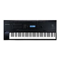
Group
Select
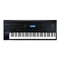
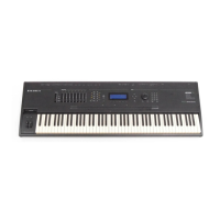
Each of the 12 channels may be assigned to one of the two
mixer outputs. These mixer outputs are designated LEFT and
RIGHT.
The channels assigned to Group A can
be
panned from left
to
right
by
moving the Group A slider
on
the front panel of the K250. Similarly,
the channels assigned to Group B can
be
panned from left to right by
moving the Group B
slider
on
the front panel of the K250.
The diagnostic will ask:
ASSIGN
TO
GROUP A?
1
If you press the YES switch
on
the front panel, the channel
will be
aSSigned
to mixer Group
A.
If you press the NO switch
on
the
front panel, the channel is assigned
to
mixer Group
B.
Kurzwell
250
Service Manual, Chapter 4
4-63
 Loading...
