This document contains proprietary information of KVH Industries, Inc. and neither this document nor said proprietary information shall be
published, reproduced, copied, disclosed, or used for any purpose without the express written permission of a duly authorized KVH
representative.
The intermediate filter stage is run at the ICB input data rate. That is, for each data sample
accepted from the gyro or accelerometer sub-system, the data is put into its intermediate
stage filter function. This generates a filter output as well. The intermediate filter runs a
biquad filter function that is always configured to use the Butterworth type (8
th
order)
coefficients, independent of output filter configuration, to implement the low-pass filter prior to
downsampling at either a 1:1, 10:1, or 100:1 ratio. The output of the intermediate
filter/downsampler is synchronous to the input and this is, therefore, an integer downsample
of the input data. The downsampling ratio is controlled by data rate and the output filter
selection. Intermediate filter cutoff is set by the data rate in very coarse steps to prevent
aliasing the downsampled data. The intermediate filtering and downsampling used at various
data rates is shown in Table 12-2.
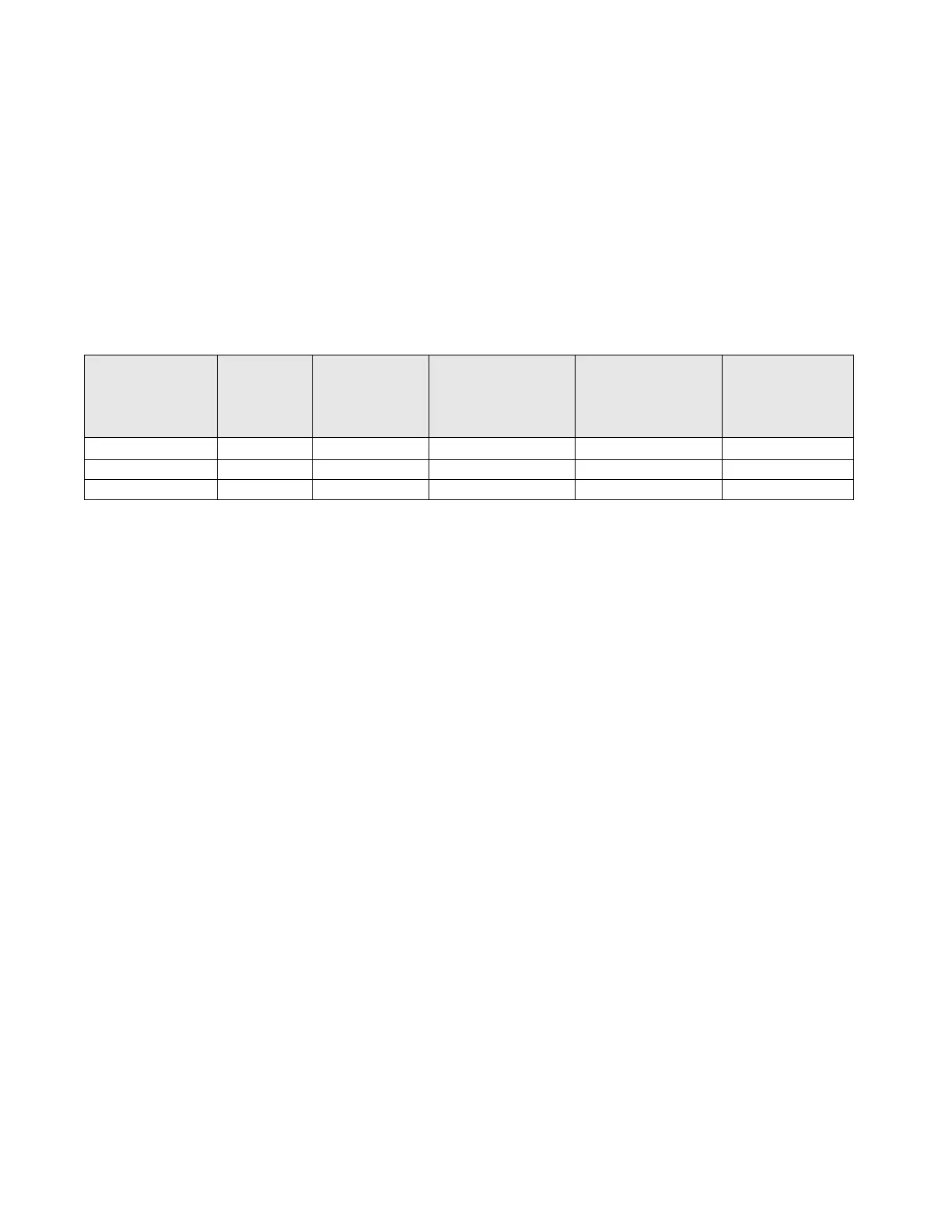
Table 12-2: Filtering and Downsampling
Gyro
Internal
Sample
Rate (Hz)
Gyro Filter
Cutoff
Frequency
(Hz)
accelerometer
Internal Sample
Rate (Hz)
accelerometer
Filter Cutoff
Frequency (Hz)
Decimation
Downsample
Ratio
12.2.3 Processing With Final Output Filter Disabled
As shown in the Signal-Processing Diagram, the FILTEN configuration determines the data
path that selects whether the intermediate stage downsampler and the final output filters are
used. Even when a user disables the filtering with the =FILTEN,0 command, the data is
passed through the intermediate stage filtering portion of the decimator, but not the
downsampler. When the final output filter is disabled, the output of the intermediate stage
filter is made available to the final output stage for arbitrary resampling and interpolation. This
is shown in the diagram as being stored into the output data containers.
12.2.4 Processing With Final Output Filter Enabled
When the final stage filtering is enabled, the intermediate downsampling process is done and
the data is passed into the user-configured final output filter. The filter output is then stored
with the timestamps into the output data containers. Since the internal sampling rates of the
gyros and accelerometers are different, they require different final stage filter coefficients,
even though they share the same final output rate.
12.2.4.1 Final Output Filter As Chebyshev/Butterworth/custom
The final output filters must be designed using the internal sampling rates defined in the table
shown in Table 12-2. The final stage filter input rate (i.e., its sampling rate) is the output of
the intermediate stage decimation. For the Chebyshev, Butterworth, and user-customized
filters, the final stage filtering is done with a 4-stage cascaded biquad process. This allows up
to an 8
th
order filter. The diagram shows this as low-pass filtering and this is the typical type
of filtering used to convert from the higher internal sample rates to the lower output rate.
However, for a custom filter, the user can define the filter coefficients as desired to implement
a pure low-pass filter or a combination of low-pass, band-pass, and/or band-reject filtering.

 Loading...