Home
KVH Industries
Satellite TV System
TracVision G6
KVH Industries TracVision G6 User Manual
4
of 1
of 1 rating
161 pages
Give review
Manual
Specs
To Next Page
To Next Page
To Previous Page
To Previous Page
Loading...
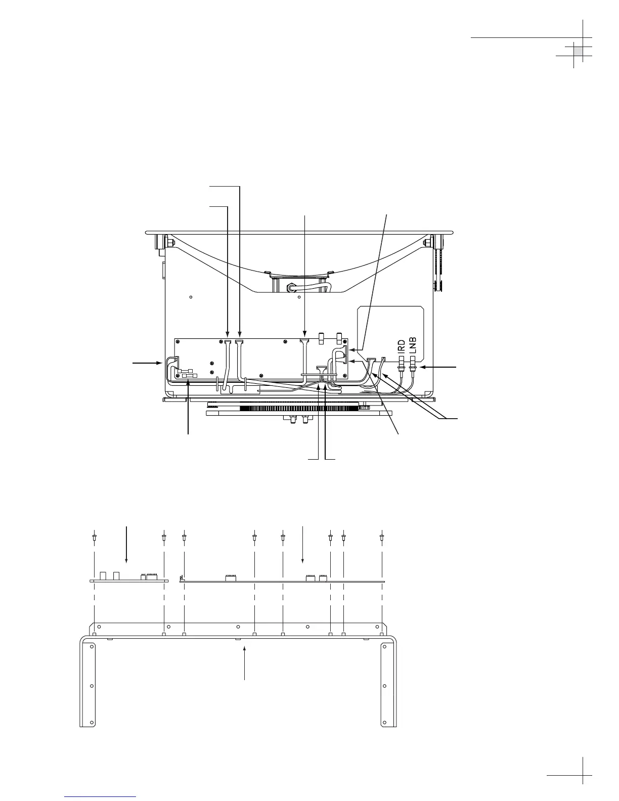
The PCBs are mounted to the antenna support frame with
machine screws and ar
e interconnected by Molex connectors.
Figure 5-3 shows the PCB arrangement and connectors, while
Figure 5-4 shows how the printed cir
cuit boards are mounted to
the support frame. Refer to these figures when r
eplacing the
PCBs.
Maintenance
54-0161
107
MAIN PCB
Azimuth Motor
Ele
vation Motor
Cable Wr
ap
(External Sensor)
RF PCB
Antenna Gyro
Azimuth Limit
Switch
Fuses
Po
w
er/Data
to Main PCB
RF Connectors
to RF PCB
Ele
vation Limit
Switch
Figure 5-4
PCB Mounting (T
op V
iew)
RF PCB
Main PCB
Suppor
t F
rame
Figure 5-3
PCB Connector Locations
(Rear V
iew)
110
112
Table of Contents
Default Chapter
3
Table of Contents
3
1 Introduction
5
Tracvision G6 System Overview
7
Tracvision G6 Components
9
Materials Provided with the Tracvision G6
10
2 Installation
11
Planning the Installation
13
Mounting the Tracvision Antenna
19
Mounting the Gyrotrac Sensor
23
Mounting the ADCU
28
Connecting the Antenna RF Cable(S)
30
Wiring the ADCU
34
Connecting the Antenna Data Cable
37
Calibrating the Sensor
46
Activating/Programming the IRD
48
Installing Satellites Using the ADCU
50
Setting the Skew Angle (European Systems Only)
59
Checking out the System
60
Changing Geographic Location
62
3 Using the ADCU Interface
63
Startup and Self-Test
65
Data Display and Accessing the Main Menu
67
Main Menu
68
Setup Display Mode
71
Set Data Outputs Mode
72
Set Configuration Mode
77
Setting Display Brightness
78
Control Compass Mode
81
Antenna Status Mode
83
Control Antenna Mode
85
Manually Controlling the Antenna
86
Restarting the Antenna
87
Installing a New Satellite Pair
88
4 Troubleshooting
95
Troubleshooting Matrix
97
Causes and Remedies for Common Operational Issues
98
Gyrotrac-Specific Issues
101
IRD Troubleshooting
102
Antenna Gyro and LNB Faults
102
Computer Diagnostics
102
Maintenance Port Parser Commands
103
5 Maintenance
105
Warranty/Service Information
107
Preventive Maintenance
107
Tracvision G6 Field Replaceable Units
108
PCB Removal and Replacement
110
Antenna Gyro Assembly
113
Azimuth Limit Switch Assembly
116
Elevation Motor and Belt Replacement
118
Antenna LNB Replacement
120
Gyrotrac Replaceable Parts
122
Preparation for Shipment
123
Appendix A System Specifications
127
Specifications
128
Appendix Badcu Flush Mount Panel Template
131
Appendix C Comprehensive Tracvision G6 System Wiring Diagram
133
Appendix D Optional Rotating Card Display
135
Appendix E Startup Data Sequences
143
Appendix F Gyrotrac Data Outputs
145
Appendix G Maintenance Port Parser Commands
151
Other manuals for KVH Industries TracVision G6
Technical Manual
157 pages
4
Based on 1 rating
Ask a question
Give review
Questions and Answers:
Need help?
Do you have a question about the KVH Industries TracVision G6 and is the answer not in the manual?
Ask a question
KVH Industries TracVision G6 Specifications
General
Brand
KVH Industries
Model
TracVision G6
Category
Satellite TV System
Language
English
Related product manuals
KVH Industries TracVision G8
144 pages
KVH Industries TracVision 4
73 pages
KVH Industries TracVision M3
2 pages
KVH Industries TracVision HD7
2 pages
KVH Industries TracVision HD11
2 pages
KVH Industries TracNet H60
42 pages
KVH Industries M5
94 pages
 Loading...


