EasyManuals Logo

KVH Industries TracVision G6 User Manual

KVH Industries TracVision G6
161 pages
To Next Page IconTo Next Page
To Previous Page IconTo Previous Page
Page #113 background imageLoading...
Page #113 background image
9. Reattach the Molex connectors and the RF cables,
making certain to connect the cables in their
original positions.
Replacing a Fuse
Two 5x20 mm, 3.15-amp, 250-volt fast-blow fuses are mounted to
the Main PCB. If one of these fuses has blown or been broken,
simply remove the bad fuse and replace with a good fuse of the
same rating.
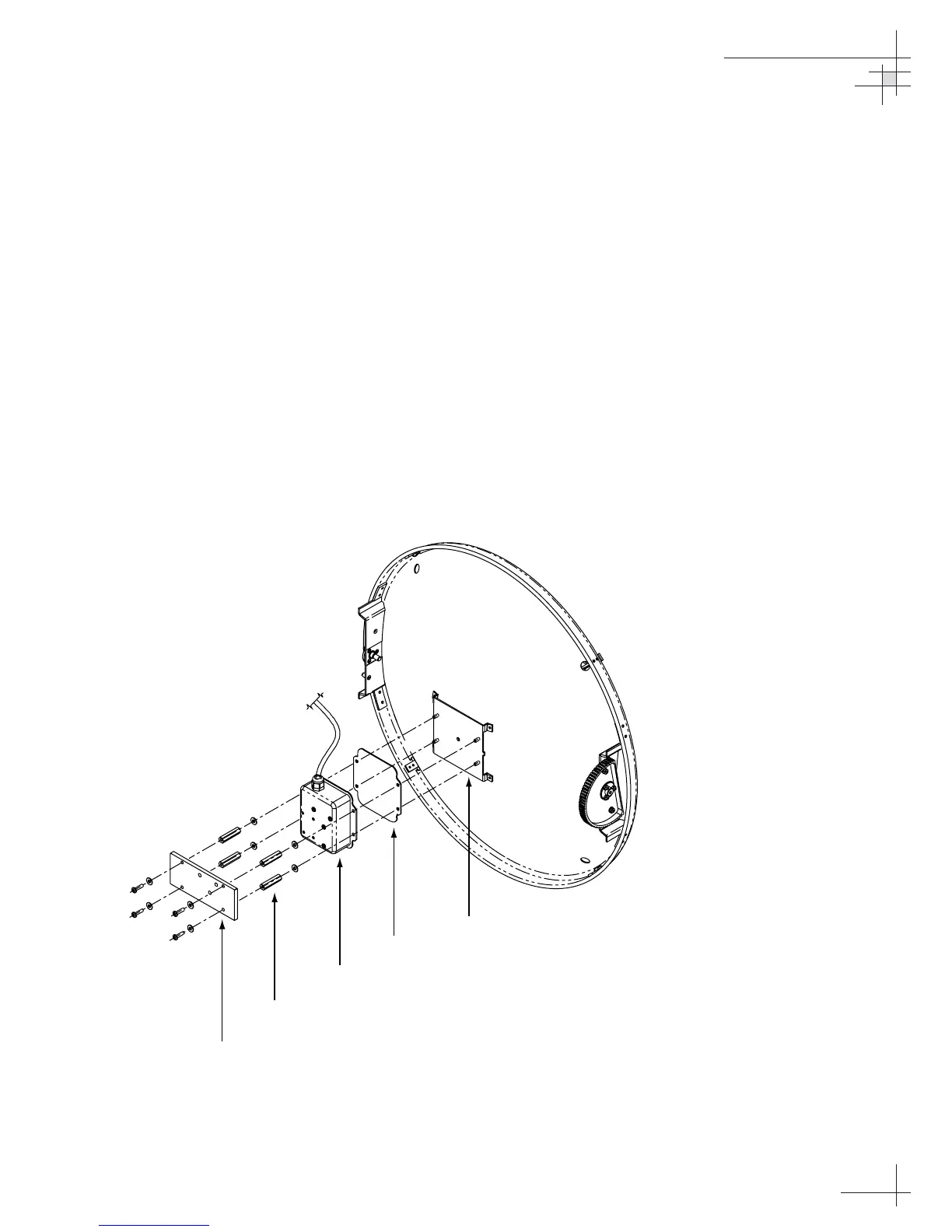
5.5 Antenna Gyro Assembly
1. Remove the PCB cover, as explained in “Removing
the PCB Cover” on page 106.
2. Remove the four screws, four washers, and the
counterweight from the end of the antenna gyro
(see Figure 5-6).
Maintenance
54-0161
109
Counterweight
Standoffs
Gyro
Gasket
Bracket
Figure 5-6
Replacing the Antenna Gyro
Assembly

Table of Contents

Other manuals for KVH Industries TracVision G6

Questions and Answers:

Question and Answer IconNeed help?

Do you have a question about the KVH Industries TracVision G6 and is the answer not in the manual?

KVH Industries TracVision G6 Specifications

General IconGeneral
BrandKVH Industries
ModelTracVision G6
CategorySatellite TV System
LanguageEnglish

Related product manuals