5.8 Antenna LNB Replacement
The LNB assembly receives power from the IRD via the RF PCB.
Be certain that the IRD is turned off or disconnected from its
power source before removing or reconnecting the LNB. The
following sections provide replacement instructions for U.S.-style
and European LNBs.
Replacing a U.S. or Latin American-style LNB
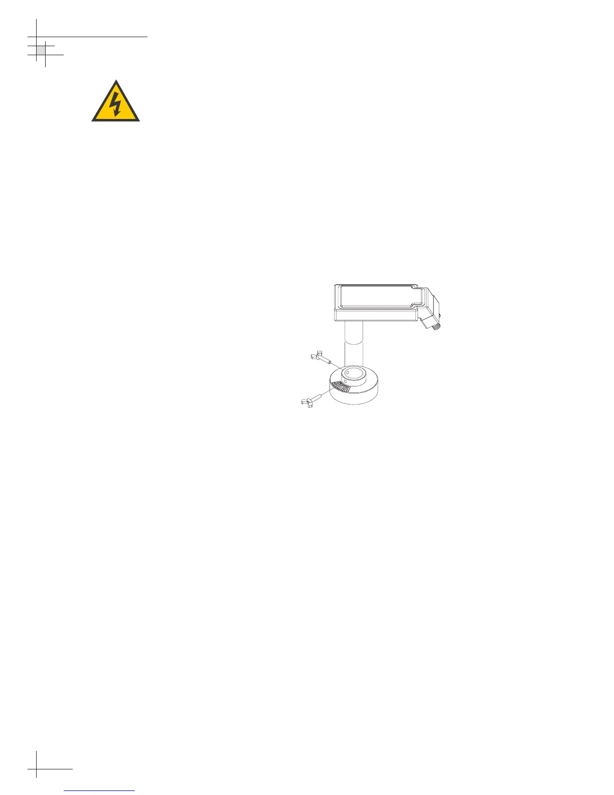
1. Disconnect both RF connectors at the LNB. Loosen
the two wing screws on the throat of the choke
feed until the LNB is free to slide out. Withdraw
the LNB as shown in Figure 5-10.
2. Insert the replacement LNB as far as it will go. Be
sure that it bottoms in the feedhorn, and be careful
not to puncture or dislodge the plastic seal
covering the LNB throat. Orient the LNB to align
with the strut holding the pair of RF cables.
3. Apply a small amount of thread-locking
compound (Loctite 425 or equivalent) to the wing
screw threads and tighten the screws to secure the
LNB in position.
4. Reconnect the RF connectors at the LNB.
54-0161
116
TracVision G6 Technical Manual
Figure 5-10
U.S.-style LNB Removal
Ensure that the IRD is turned off or
disconnected from its power source
before removing or reconnecting
the LNB.
 Loading...


