2JL/2JJ/2JG/2JD
1-2-19
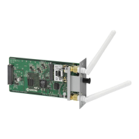
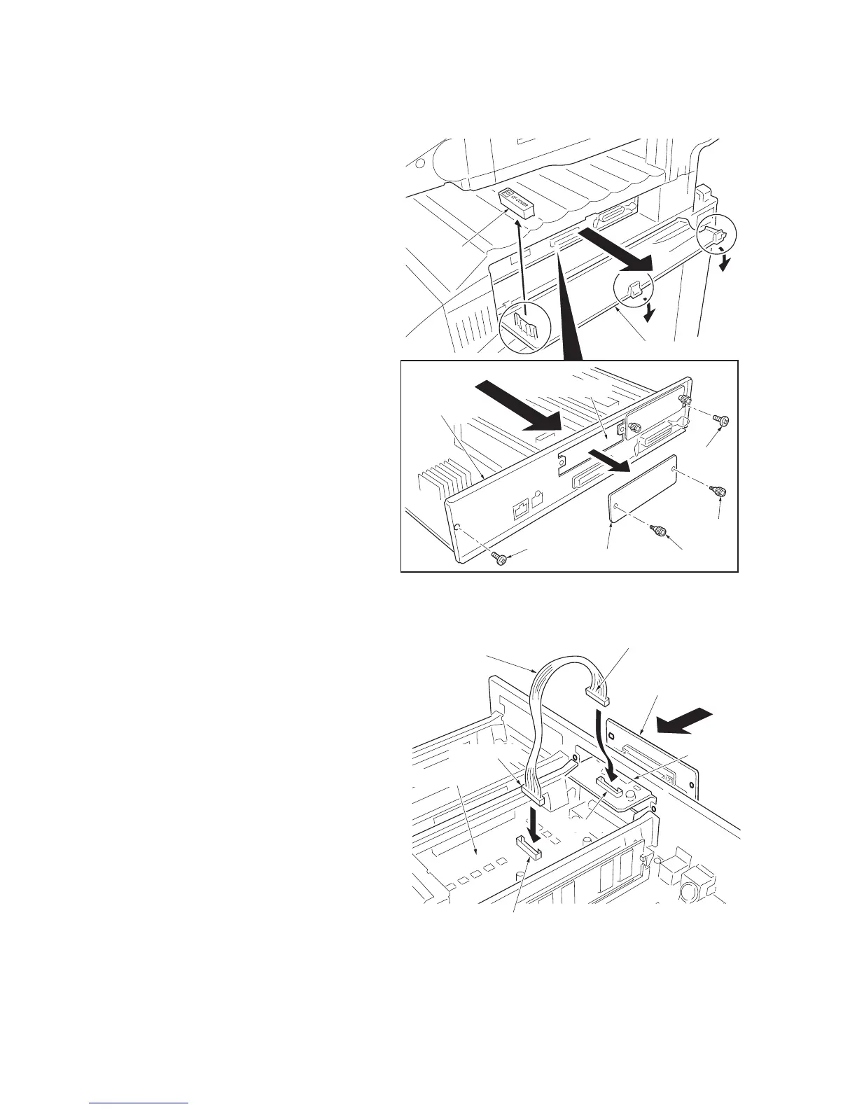
1-2-7 Installing the serial interface board (option)
Procedure
1. Turn the main power switch off and discon-
nect the power cord plug from the AC outlet.
2. Open the interface cover.
3. Remove the CF cover.
4. Remove the two screws and then remove
the printer PWB.
Remove the PWB carefully not to allow its
bottom come in contact with the three pro-
trusions on the interface cover.
5. Remove the two screws and then remove
the slot cover of slot (OPT).
Figure 1-2-28
6. Insert the serial interface board into the slot
(OPT).
7. Connect the cable’s connector (A) to the
serial interface board’s connector.
8. Connect the cable’s connector (B) to the
printer PWB’s connector (YC9).
Figure 1-2-29
Interface cover
CF cover
Screw
Screw
Screw
Slot cover
Printer PWB
Screw
Slot (OPT)
Serial interface board
Connector (YC9)
Slot (OPT)
Connector (A)
Cable
Printer PWB
Connector (B)
Connector
 Loading...