KEW6310 4.2.1 Basic Setting
KEW6310 4.8
Setting for Clamp sensor
Model names and rated currents of Clamp sensors are listed as follows.
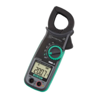
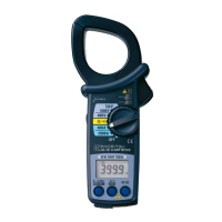
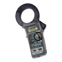
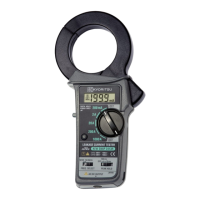
Clamp sensors for
Power measurement
Leakage Clamp sensor
8128
50A type
8141
1A type
8127
100A type
8142
1A type
8126
200A type
8143
1A type
8125
500A type
8146
10A type
8124
1000A type
8147
10A type
8129
3000A type
8148
10A type
* Default value (or after system reset) : 8125
* Clamp sensors for measurements other than power are available only at
following wiring configurations.
Number of available Clamp sensor depends on a wiring configuration to be measured.
① 1P2W×1
1ch
② 1P2W×2 1ch 2ch
③ 1P2W×3 1ch 2ch 3ch
④ 1P2W×4 1ch 2ch 3ch 4ch
⑤ 1P3W×1
⑧ 3P3W×1
1,2ch
⑥ 1P3W×2
⑨ 3P3W×2
System 1(1,2ch) System 2(3,4ch)
⑦ 1P3W×1+2A
⑩ 3P3W×1+2A
1,2ch 3ch 4ch
⑪ 3P3W3A
⑫ 3P4W×1
1,2,3ch
⑬ 3P4W×1+1A 1,2,3ch 4ch
4A 1ch 2ch 3ch 4ch
* Default value (or after system reset) : ⑩ 1,2,ch 3, 4ch
* Channels highlighted in light yellow are applicable only to Clamp sensors for
power measurement.
* Channels highlighted in gray are applicable to Clamp sensors for power
measurement and Leakage Clamp sensors.
0

 Loading...