TX
TXTX
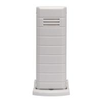
TX38U-IT
38U-IT38U-IT
38U-IT Wireless
Wireless Wireless
Wireless 915
915915
915 MHz Temperature
MHz Temperature MHz Temperature
MHz Temperature
transmitter
transmittertransmitter
transmitter
The TX38U-IT temperature transmitter measures the outdoor temperature and
transfers the data to the temperature station.
INVENTORY OF CONTENTS
INVENTORY OF CONTENTSINVENTORY OF CONTENTS
INVENTORY OF CONTENTS
1. One TX38U-IT Temperature transmitter
2. Mounting hardware
3. Instruction manual and warranty card.
ADDITIONAL EQUIPMENT (not included)
• Two fresh AAA, IEC LR3, 1.5V Alkaline batteries.
• Important Notes on Set-up and Operation The Temperature transmitter
should be placed in a dry, shaded area. Avoid direct sun, as that will cause
incorrect readings.
• Fog and mist will not harm your Temperature transmitter but direct rain
must be avoided.
The temperature sensor has a range of 330 feet (100 m). Keep in mind
that the 330 feet is in open air with no obstructions and that radio waves
DO NOT curve around objects. Actual transmission range will vary
depending on what is in the path of the signal. Each obstruction (roof,
walls, floors, ceilings, thick trees, etc.) will effectively cut signal range in
half.
Example: A wireless weather/ temperature station with a 330 feet (100 m)
range is mounted on an interior wall, so that the signal has to pass through
one interior wall, one exterior wall, and across the 10 feet (3 m) width of the
room between the 2 walls. The first wall will reduce the range to 165 feet
(50 m), and the second wall will reduce the range to 87 feet (26.5 m).
Factoring in the 10 foot room, this leaves a maximum of 77 feet (23.5 m) of
remaining signal range.
This allowance is typically enough for a frame wall with non-metallic siding;
however certain materials can reduce range even further. Metal siding,
stucco, and some types of glass can reduce signal range by as much as ¾
or more, compared to the ½ reduction typical of most obstructions. It is
possible to receive a signal through these materials, however maximum
range will be much less due to their tendency to absorb or reflect a much
larger portion of the sensor’s signal.
• The Temperature transmitter transmits a signal about every 4 seconds.
After the batteries have been installed, the indoor temperature station will
search for the signal for a duration of few minutes. If there is no
temperature reading in the OUTDOOR LCD after 5 minutes, user shall
make sure the units are within range of each other, or repeat the battery
installation procedure.
• If a button is pressed before the indoor temperature station receives the
signal from the Temperature transmitter, you will need to follow the battery
installation procedure again.
SETTING UP
SETTING UPSETTING UP
SETTING UP
When one transmitter is to be used
1. First, insert the batteries to the temperature transmitter (see “Battery
Installation” below).
2. Within 2 minutes of powering up the transmitter, insert the batteries to the
Temperature Station (see “Battery Installation” below). Once the
batteries are in place, all segments of the LCD will light up briefly.
Following the indoor temperature and the time as 12:00 will be displayed.
If they are not shown in LCD after 60 seconds, remove the batteries and
wait for at least 60 seconds before reinserting them. Once the indoor data
is displayed user may proceed to the next step.
3. After the batteries are inserted, the Temperature Station will start
receiving data signal from the transmitter. The outdoor temperature
should then be displayed on the Temperature station. If this does not
happen after 5 minutes, the batteries will need to be removed from both
units and reset from step 1.
4. In order to ensure sufficient 915 MHz transmission however, this should
under good conditions be a distance no more than 330 feet (100 meters)
between the final position of the Temperature Station and the transmitter
Adding additional remote transmitter (using more than 1 transmitter)
1. User shall remove all the batteries from the temperature station and
transmitters and wait 60 seconds if setting has been done with one
transmitter before.
2. Insert the batteries to the first transmitter.
3. Within 2 minutes of powering up the first transmitter, insert the batteries
to the Temperature Station. Once the batteries are in place, all segments
of the LCD will light up briefly. Following the indoor temperature and the
time as 12:00 will be displayed. If they are not shown in LCD after 60
seconds, remove the batteries and wait for at least 60 seconds before
reinserting them.
4. The outdoor temperature from the first transmitter (channel 1) should
then be displayed on the Temperature station. Also, the signal reception
icon will be displayed. If this does not happen after 5 minutes, the
batteries will need to be removed from both units and reset from step 1.
5. Insert the batteries to the second transmitter as soon as the outdoor
temperature readings from the first transmitter are displayed on the
temperature station.
Note:
User shall insert the batteries into the second transmitter within 45 seconds of
reception of the first transmitter.
6. The outdoor temperature from the second transmitter and the "channel 2"
icon should then be displayed on the Temperature station. If this does not
happen after 5 minute, the batteries will need to be removed from all the
units and reset from step 1.
7. Insert the batteries to the third transmitter as soon as the "channel 2" icon
and outdoor data are displayed on the temperature station. Then within 5
minutes, the channel 3 outdoor data from the third transmitter will be
displayed and the channel icon will shift back to "1" once the third
transmitter is successfully received. If this is not happen, user shall
restart the setting up from step 1.
Note: User shall insert the batteries into the third transmitter within 45 seconds
of reception of the second transmitter.
8. In order to ensure sufficient 915 MHz transmission however, this should
under good conditions be a distance no more than 330 feet (100 m)
between the final position of the Temperature Station and the transmitter
MPORTANT:
Transmission problems will arise if the setting for additional sensors is not
followed as described above. Should transmission problems occur, it is
necessary to remove the batteries from all units and start again the set-up from
step 1.
B
BB
BATTERY INSTALLATION
ATTERY INSTALLATIONATTERY INSTALLATION
ATTERY INSTALLATION
Temperature Station
1. Lift up the battery compartment cover.
2. Observing the correct polarity install 2 AA, IEC LR6, 1.5V batteries.
The batteries will fit tightly (to avoid start-up problems make sure they do
not spring free).
3. Replace compartment cover.
Remote Temperature transmitter
1. Remove the battery cover by sliding the cover down.
2. Observing the correct polarity install 2 AAA, IEC LR3, 1.5V batteries. The
batteries will fit tightly (to avoid start-up problems make sure they do not
spring free).
3. Replace the battery cover by sliding upwards. Be sure battery cover is on
securely.
Note:
• If the signal reception is not successful on the first frequency of 915MHz
for 45 seconds, the frequency is changed to 920MHz and the learning is
tried for another 45 seconds. If it is still not successful the reception is
tried for 45 seconds on 910MHz. This will also be done during re-
synchronization.
• Detailed Set up procedures of the Temperature Station and the
Transmitter refer to the main operation manual of Temperature Station.
MOUNTING
MOUNTINGMOUNTING
MOUNTING
THE TEMPERATURE TRANSMITTER
The Temperature transmitter can be mounted onto a wall with the use of screws
MOUNTING WITH SCREWS
1. Remove the mounting bracket from the Temperature transmitter.
2. Place the mounting bracket over the desired location.
3. Through the two screw holes of the bracket, mark the mounting surface
with a pencil.
4. Screw mounting bracket onto the mounting surface. Ensure that the
screws are tight against the bracket.
5. Insert the Temperature transmitter into the bracket.