G=2 ±10 volts
G=4 ±5 volts
G=5 ±4 volts
G=8 ±2.5 volts
G=10 ±2 volts
G=16 ±1.25 volts
G=20 ±1 volt
The reason the range is ±20 volts at G=1 is that, for example, AI0 could be +10 volts and AI1 could be -10 volts giving a difference
of +20 volts, or AI0 could be -10 volts and AI1 could be +10 volts giving a difference of -20 volts.
The PGA (programmable gain amplifier, available on differential channels only) amplifies the AI voltage before it is digitized by the
A/D converter. The high level drivers then divide the reading by the gain and return the actual measured voltage.
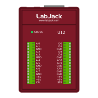
Figure 2-2 shows a typical single-ended connection measuring the voltage of a battery. This same measurement could also be
performed with a differential connection to allow the use of the PGA. In general, any single-ended measurement can be performed
using a differential channel by connecting the voltage to an even-numbered analog input, and grounding the associated odd-
numbered analog input (as shown by the dashed connection to AI1 in Figure 2-2).
Figure 2-2. Single-ended measurement.
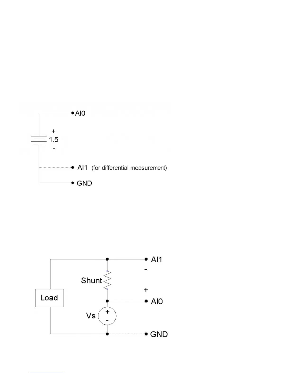
Figure 2-3 shows a typical differential connection measuring the voltage across a current shunt. A differential connection is
required when neither leg of the shunt is at ground potential. Make sure that the voltage of both AI0 an AI1 with respect to ground is
within ±10 volts. For instance, if the source (Vs) shown in Figure 2-3 is 120 VAC, the difference between AI0 and AI1 might be
small, but the voltage from both AI0 and AI1 to ground will have a maximum value near 170 volts, and will seriously damage the
LabJack.
Whether or not the ground (GND) connection is needed (Figure 2-3) will depend on the nature of Vs.
Figure 2-3. Differential measurement.
 Loading...