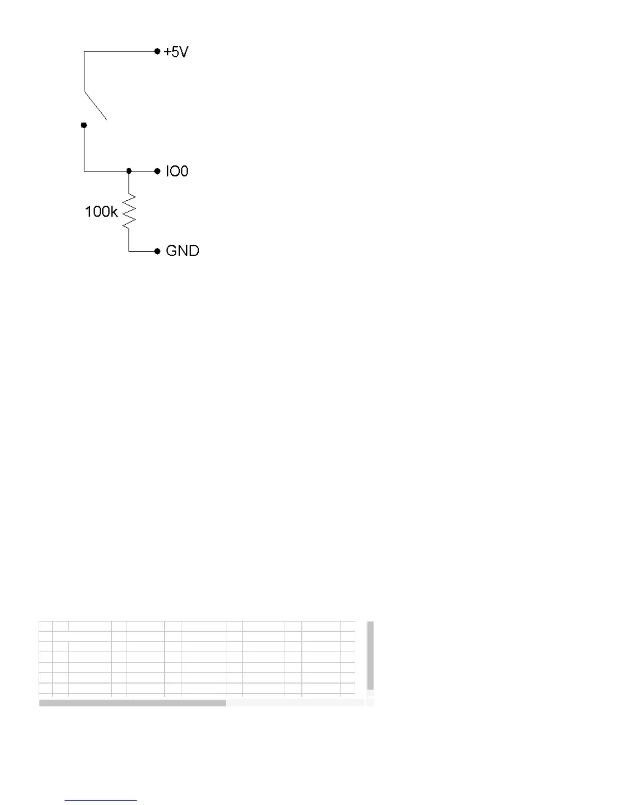
Figure 2-5. IO used to detect the state of a switch.
While providing overvoltage/short-circuit protection, the 1.5 kΩ series resistor on each IO pin also limits the output current
capability. For instance, with an output current of 1 mA, the series resistor will drop 1.5 volts, resulting in an output voltage of about
3.5 volts.
Software
The easy functions EDigitalIn or EDigitalOut are used to read or set the state of one digital line, and both take up to 20 ms to
execute.
The functions AOUpdate and DigitalIO are used to set the direction, set the state, and/or read the state, of each IO pin. Both of
these functions take up to 20 ms to execute, providing a maximum update rate of about 50 Hz per pin.
The function AISample can set/read the state of each IO, but setting the state will have no effect unless the IO have been
configured as outputs using another function. The function Counter reads the state of each IO.
The functions AIBurst and AIStreamRead, take a reading of the IO states and return it with the analog data. The states of the 4 IO
are read simultaneously every 4 samples, providing a data rate of up to 2048 Hz per pin for burst mode, or 300 Hz per pin for
stream mode. For 1 or 2 channel scans, duplicate data (4x or 2x) will be added to the read array such that the size is numScans.
2.4 - D0-D15
Connections to 16 of the LabJack’s 20 digital I/O are made at the DB25 connector, and are referred to as D0-D15. These 16 lines
have no overvoltage/short-circuit protection, and can sink or source up to 25 mA each (total sink or source current of 200 mA max
for all 16). This allows the D pins to be used to directly control some relays. All digital I/O are CMOS output and TTL input except
for D13-D15, which are Schmitt trigger input. Each D pin has a 1 MΩ resistor connected to ground.
All digital I/O are set to input on power-up or reset.
These digital I/O can detect the state of a switch using the same circuit shown in Figure 2-5.
Because the D pins have no overvoltage/short-circuit protection, the user must be careful to avoid damage. A series
resistor can provide substantial protection for these pins (see the CB25 datasheet). The following are examples of
things that could damage a D pin and/or the entire LabJack:
 Loading...