EasyManua.ls Logo

Laguna Tools Smartshop II User Manual

Laguna Tools Smartshop II
51 pages
To Next Page IconTo Next Page
Page #1 background imageLoading...
Page #1 background image
Smartshop II Manual
LAGUNA TOOLS
2072 Alton Parkway
Irvine, California 92606
Ph: 800.234.1976
www.lagunatools.com
SmartShop ll 4'x8' - 6 HP Spindle 10HP Vacuum CNC Router
SmartShop ll 4'x8' - 7.5HP Spindle 10HP Vacuum CNC Router
SmartShop ll 5'X10' - 7.5HP spindle CNC Router
SmartShop ll 4'x8' - 11HP HSD Spindle 10HP Vacuum CNC Router w/ATC
SmartShop ll 5'x10' - 11HP HSD Spindle 10HP Vacuum CNC Router
MCNC SS2 4X8 6 HP LIQUID COOLED
MCNC SS2 4X8 liquid ATC-0158
MCNC SS2 5X10 Liquid ATC-0158
MCNC SS2 4X8 HSD ATC-0158
MCNC SS2 5X10 HSD ATC-0158
Model No.
© 2018, Laguna Tools, Inc. LAGUNA® and the LAGUNA Logo® are the registered trademarks of Laguna Tools, Inc. All rights reserved.
Question and Answer IconNeed help?

Do you have a question about the Laguna Tools Smartshop II and is the answer not in the manual?

Laguna Tools Smartshop II Specifications

General IconGeneral
TypeCNC Router
Working Area24" x 36"
Table Type/Table SizeAluminum T-Slot Table
Spindle Speed18000 RPM
Cooling SystemAir-Cooled

Summary

Safety Rules

Limited Warranty

Noise Emission

Receiving the Machine

Machine Specifications

Introduction to CNC Machines

Laguna SmartShop II Machine Parts

Machine Table

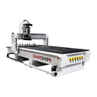
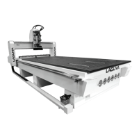
Describes the bed, frame, and T-slots for fixturing.

Gantry

Explains gantry structure and motion components.

Electro-Spindle Assembly

Details the spindle movement mechanism.

Tool Rack ATC

Describes the automatic tool changer system.

Additional Accessories that are included with the Machine

Machine Installation

Machine Location

Guidelines for selecting the installation area.

Unpacking the Machine

Step-by-step instructions for safe unpacking.

Assembly & Setup

Cleaning the Machine

Instructions for removing grease and lubricating.

Fitting the Dust Hose

Guidance on attaching and managing the dust hose.

Electrical Connections

Compressed Air Connection

Connecting the Vacuum Pump

Installing the Router Bit in the Tool Holder

Manual Tool Release

Selecting the Correct Router Bit

Straight Router Bits

Describes standard router bits.

Up Shear Router Bits

Explains bits with upward spiraled flutes.

Combination (Compression) Router Bits

Details bits combining up/down shear designs.

Form Router Bits

Describes bits with standard profiles.

Working With Vacuum Tables and Spoil Boards

Spoil Board Material and Precautions

Discusses using MDF for vacuum fixturing.

Functions of the Spoil Board

Explains spoil board roles in protection and vacuum transfer.

Spoil Board Preparation

Details sourcing, cutting, and sealing spoil boards.

Spoil Board Use

Covers cleaning and managing cuts on spoil boards.

Precautions Regarding Spoil Boards

Addresses moisture, warpage, and re-fly-cutting.

Automatic Tool Changer (ATC)

The Automatic Tool Touch-Off system

Describes automatic tool length measurement.

The Laguna Touch CNC Controller

Main Button Descriptions

Details the function of each controller button.

RUN screen

Homing the machine

Explains homing as the initial step after power-up.

Machine Coords

Dropdown for selecting dimension sets for axis DROs.

Start at Tool

Allows starting programs from a specific tool.

RUN/OVERRIDES screen

MANUAL/Screen 1 (Jog and Manual Spindle Control)

CONT. JOG

Selects continuous jog mode based on speed.

STEP JOG

Selects step jog mode based on resolution.

Axis Selection for Jogging

Buttons to choose the axis for jogging.

MANUAL/Screen 2

MANUAL/Screen 3

HOME speeds

Fields for setting X, Y, Z home speeds.

SPINDLE DELAY

Time delay for spindle to reach speed.

SPEED LIMITs

Top speeds for rapid moves at 100% feed rate.

Home switches indicators

Verifies function of individual home switches.

PROGRAM screen

ACCESS USB

Opens USB drive with stored programs.

ACCESS CF CARD

Lists programs on the controller's CF card.

Program Copy Function

Moves programs between storage locations.

TOOLS screen

Tool selection and touch-off

Selects tools and performs touch-off for length.

EXECUTE TOUCH OFF button

Initiates the tool touch-off routine.

Teach Tool Length

Manually performs tool touch-off.

Set Tool in Spindle field

Indicates the currently loaded tool.

TOOLS/Screen 2

ZSPOIL field

Input for spoil board thickness to adjust Z Zero.

TOOLS/COORDS Screen 1

RESET RELATIVE

Tape measure function for zeroing axes.

TEACH ZPO (Zero Point Offset)

Sets work offsets by jogging to the origin.

TOOLS/COORDS Screen 2

TOOLS/COORDS Screen 3 (Coords Setup)

ALARM Screen 1 (CNC, System, Machine Faults)

ALARM Screen 2 (Axis Errors)

Getting Started

Setting the Zero Point Offset

Steps to prepare spoil board and set origin.

Manual Jogging Operations

Using controller buttons for positioning.

Loading Programs and Tools

Procedures for loading programs and inserting tools.

TOOL TOUCH-OFF PROCEDURE

Tool Selection and Touch-Off Initiation

Select tool and initiate touch-off.

Manual and Automated Tool Measurement

Covers manual touch-off and automated measurement processes.

Spoil Board Thickness Input and Homing

Inputting ZSPOIL and homing for update.

Machine Maintenance

Daily Checks

Routine checks: cleaning, lubrication, cutters.

Weekly Checks

Additional checks for cutters, machine, dust.

Oiling the Machine

Guidance on central oiler use and oil type.

Troubleshooting

Machine will not start

Checks for power, switches, and wiring.

Motor issues

Diagnosing motor start and overheating problems.

Spindle slows down during a cut

Identifies dull tools or fast feed rate.

Machine vibrates

Recommends leveling the machine.

B&R G-Code Functions

Related product manuals