www.lairdtech.com/bluetooth
25
© Copyright 2018 Laird. All Rights Reserved
Americas: +1-800-492-2320
Europe: +44-1628-858-940
Hong Kong: +852 2923 0610
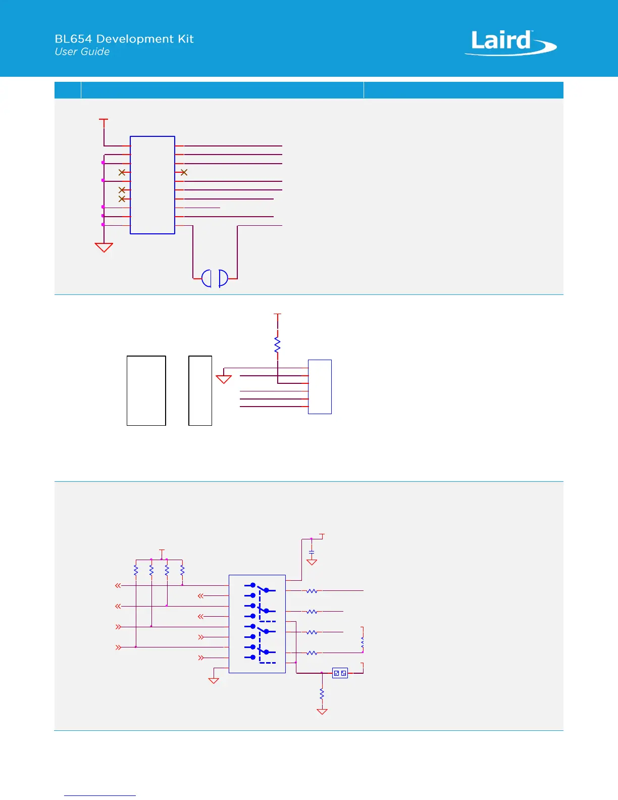
Plated Through Holes or Header Connector
BL654 Module Signals Exposed
J46 is NOPOP but is compatible to same
connector on Nordic development board and
brings out same signals.
SIO_41 on BL654 is SPI_CLK (as an
alternative function) is disconnected from
J46 on devboard by open solderbridge SB23.
SIO_41 on BL654 is directly connected to U2
(Eeprom) pin6 on devboard.
Serial Port plated holes for access:
Jumper in J35 selects between BL654 UART
routed to FTDI Atmel MCU:
No Jumper on J35 (default)
Routes SIO_05 (RTS) to FTDI CTS
Routes SIO_06 (TX) to FTDI RX
Routes SIO_07 (CTS) to FTDI RTS
Routes SIO_08 (RX) to FTDI TX
Jumper on J35 (Route to Atmel)
Routes SIO_05 (RTS) to IMCU_CTS
Routes SIO_06 (TX) to IMCU_RxD
Routes SIO_07 (CTS) to IMCU_RTS
Routes SIO_08 (RX) to IMCU_TxD
VDD_VSRC_nRF
TRACECLK
TRACEDATA0
TRACEDATA1
TRACEDATA2
TRACEDATA3
SB23
NOPOP (Solderbridge_Open)
1
1
2
2
GND
SWDCLK_BLE
SIO_32_SWO_BLE
SWDIO_BLE
SIO_11
nRESET_BLE
SIO_07
SIO_12
J46
NOPOP (PIN HEADER,1.27mm 2X10P)
1 2
3 4
5 6
7 8
9 10
11
13
15
17
19
12
14
16
18
20
Eeprom_SCK_SIO_41
SIO_32_SWO_BLE
SIO_06
R1
NOPOP (0R)
Module pin BL654 UART Data Flow
SIO_06 Module_TX Output
SIO_08 Module_RX Input
SIO_05 Module_RTS Output
SIO_07 Module_CTS Input
SIO_07
SIO_08
VDD_VSRC_nRF
SIO_05
FTDI (USB to TTL 232 Cable)
GND
USB_CTS
VCC
USB_TX
USB_RX
USB_RTS
GND
RTS
VCC
RX
TX
CTS
J1
NOPOP (PIN HEADER,2.54mm 1X6P)
1
1
2
2
3
3
4
4
5
5
6
6
GND
BL654 UART J35
routed to FTDI: No Jumper in J35 (default).
routed to Atmel: Fit Jumper in J35.
IMCU_CTS
IMCU_RxD
C8
0.1uF,16V
GND
IMCU_RTS
IMCU_TxD
USB_CTS
Module_CTS
VDD_VSRC_nRF
R7
10K
R6 0R
R9 0R
R12 0R
R21 0R
USB_RX
R19
10K
PIN HEADER,2.54mm 1X2P
J35
1
1
2
2
USB_DETECT Pins connect
High 1A-->1B1,
2A-->2B1,
3A-->3B1,
4A-->4B1
Module_RX
GND
SIO_08
VDD_VSRC_nRF
SIO_05
SIO_06
SIO_07
VDD_VSRC_nRF
USB_TX
USB_RTS
VDD_VSRC_nRF
U15
Dual DPDT,1.65V~4.45V
1B0
1
1B1
15
2B0
5
2B1
3
1A
16
2A
4
1S
2
3B0
9
3B1
7
4B0
13
4B1
11
3A
8
4A
12
2S
10
GND
6
VCC
14
Module_RTS
Module_TX
R2
10K
GND
R3
10K
R10
10K
R11
10K
 Loading...
