The BL654 development board provides for simple and hassle-free connectivity to a wide range of sensors, but also includes
several on-board sensors and options to enable a developer to test functionality straight out of the box.
In the smartBASIC application code written to use sensors on the development board, including the Temperature sensor
(U1) – analog output, SPI EEPROM (U2), I2C RTC chip (U16), LED1(D1), LED2(D2), LED3(D3), LED4(D4) Button1(SW1),
Button2(SW2), Button3(SW9) and Button4(SW10) the SIO pins direction and type must be set in the smartBASIC application
to override the defaults in the BL654 firmware.
For more information on these sample applications, see GitHub smartBASIC sample applications repository on the BL654
product page at https://github.com/LairdCP/BL654-Applications.
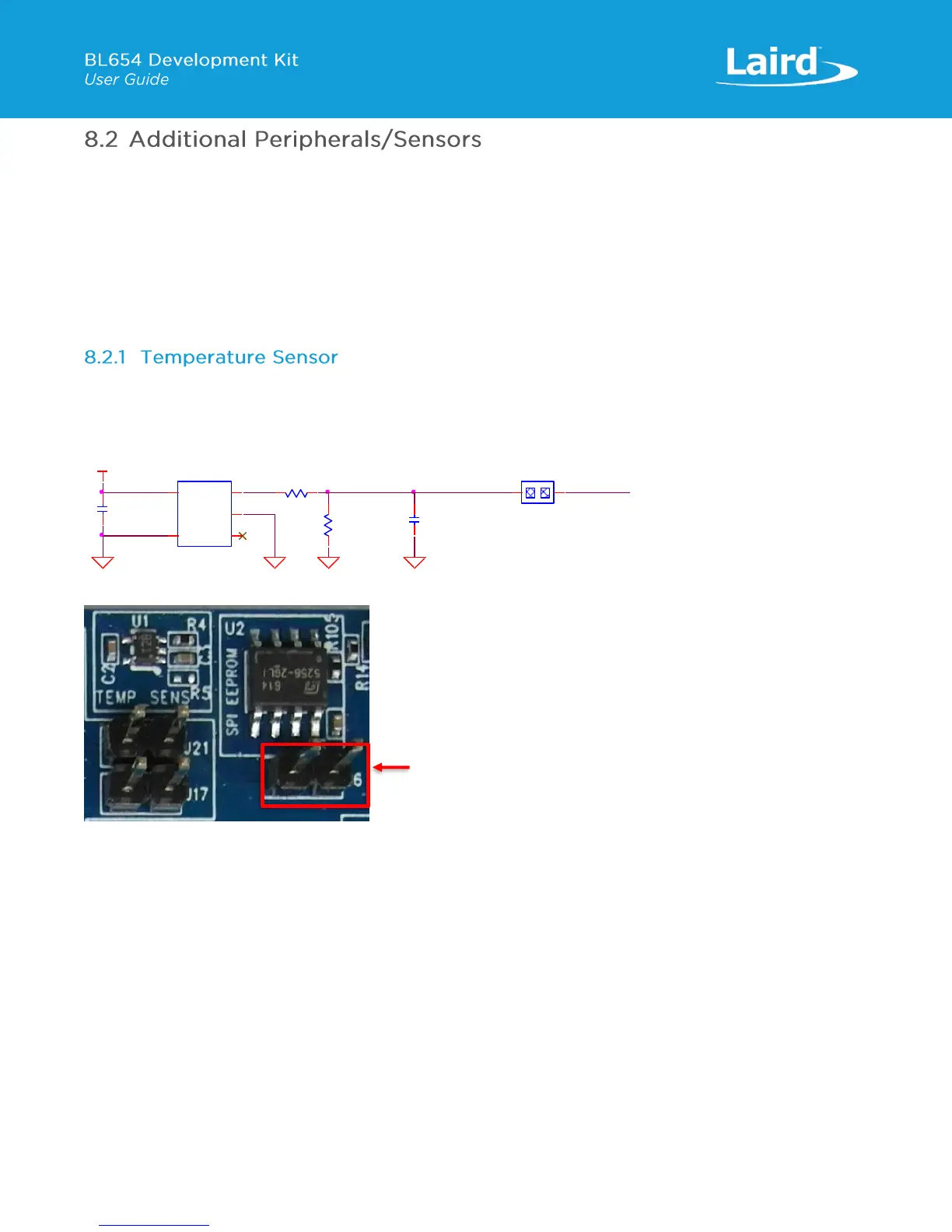
The temperature sensor (U1) by default is connected to the BL654 module as jumper on J6 pin bridges TEMP_SENS and
SIO_03.
The on-board temperature sensor (TI LM20BIM7 - www.ti.com/lit/ds/symlink/lm20.pdf) has an analogue output that can be
connected to BL654 module pin SIO_03; but since the LM20BIM7 has an analogue output, the BL654 module SIO_03 digital
pin (DIO) must be configured as AIN analogue input (ADC). To configure the SIO_03 pin from DIO pin to Alternate function
AIN, see the example file “ts.temperature.sensor.sb” in the GitHub smartBASIC sample applications repository on the BL654
product page at https://github.com/LairdCP/BL654-Applications
Key specifications of the LM20BIM7 are as follows in Table 9.
 Loading...
